
Positioning mechanism of circular pipe bending device

A bending device and positioning mechanism technology, applied in the direction of feeding device, positioning device, storage device, etc., can solve the problems of large difference, great influence on bending accuracy, and large product assembly error

Inactive Publication Date: 2015-09-02
ZHEJIANG LIFAN FURNITURE
View PDF6 Cites 1 Cited by
  • Summary
  • Abstract
  • Description
  • Claims
  • Application Information

AI Technical Summary

Problems solved by technology

[0002] Round steel pipe is a commonly used section steel, which is widely used in various fields. The more common ones are construction and industrial fields. At the same time, many household products also use round steel pipes as the skeleton of tables and chairs. In actual use, consider For strength or shape matching problems, this type of steel pipe must be bent. Several issues need to be considered when bending round pipes: 1. Accurate positioning of the bending point. If the bending point deviates greatly, it is easy to cause The problem of large assembly errors or even inability to assemble late-stage products; 2. Springback phenomenon. Many round steel pipes are prone to springback after being bent. There are many stamping bendings. Stamping bending is to use the momentum to quickly bend. When the momentum disappears, the round steel pipe will rebound at a certain angle due to the self-recovery of its own metal; 3. The clamping degree of the round pipe, if the round pipe is in the There is looseness during the bending process, which has a great influence on the bending accuracy

Method used


Image

  • Positioning mechanism of circular pipe bending device
  • Positioning mechanism of circular pipe bending device
  • Positioning mechanism of circular pipe bending device

Examples


Embodiment Construction

[0014] The specific embodiment of the present invention will be further described below in conjunction with accompanying drawing:

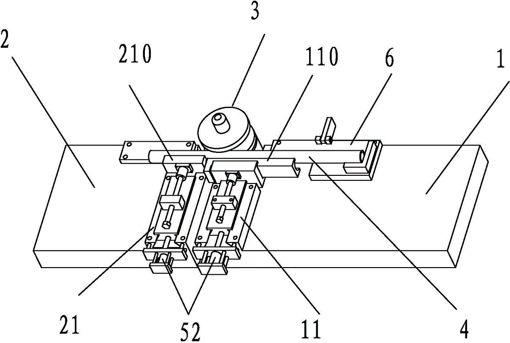
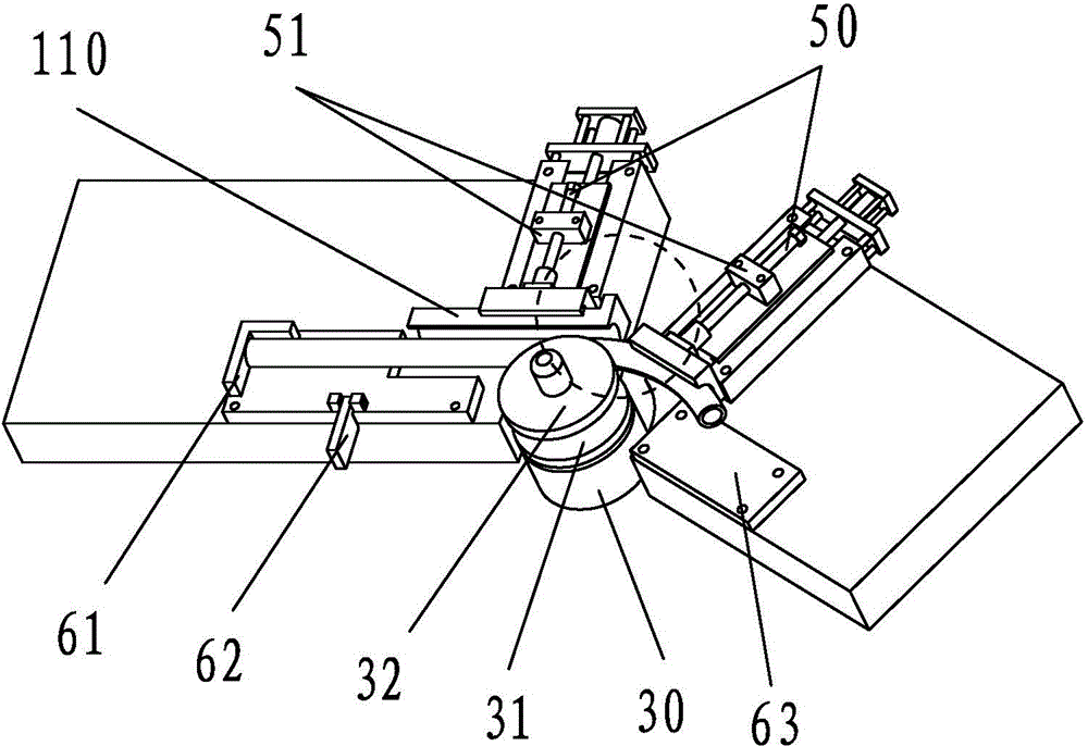
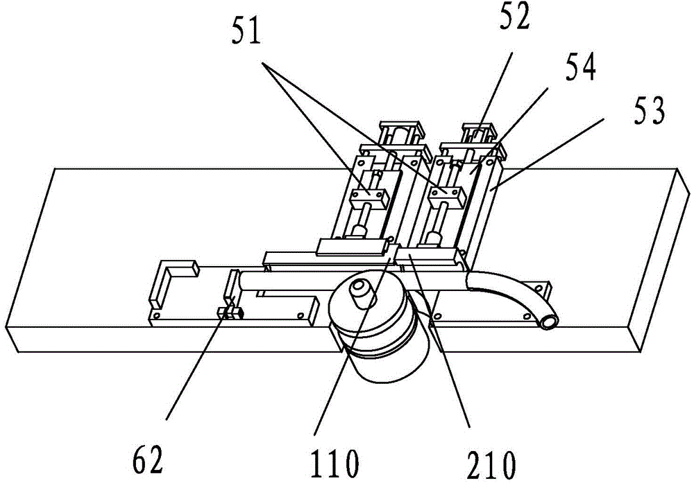
[0015] Such as Figure 1 to Figure 4 As shown, a positioning mechanism of a round pipe bending device includes a fixed worktable 1 and a rotatable rotating worktable 2, and a freely rotating rotating round table 3 is arranged between the fixed workbench and the rotating worktable. In this embodiment, The rotating table rotates around the rotating table as the center. One end of the round pipe 4 is positioned on the fixed table, and the other end is fixed on the rotating table. The side wall of the rotating table is provided with an arc concave surface 31, and the outer wall of the round pipe is also an arc surface. , the circular arc surface is just accommodated in the circular arc concave surface. When the circular tube is actually positioned, the middle part of the circular tube fits in the circular arc concave surface of the side wall of the ro...


PUM


Abstract

The present invention discloses a positioning mechanism of a circular pipe bending device. The positioning mechanism comprises a stationary work table and a rotary work table capable of rotating; a freely rotating rotary circular bench is disposed between the stationary work table and the rotary work table; the circular pipe is positioned on the stationary work table; the circular pipe is bended in a rotation direction when the rotary work table rotates along a plane; the stationary work table is provided with a first clamping device for clamping the front portion of the circular pipe; the first clamping device comprises a first chuck and a driving device for driving the first chuck; the rotary work table is provided with a second clamping device for clamping the rear portion of the circular pipe; the second clamping device comprises a second chuck and another driving device for driving the second chuck; a positioning bench for positioning the circular pipe is disposed on the stationary work table; and the head bend of the positioning bench is provided with an L-shaped positioning strip. The positioning mechanism is accurate in positioning and good in clamping effect, and is not easy to loosen.

Description

technical field [0001] The invention relates to a positioning mechanism of a round pipe bending device. Background technique [0002] Round steel pipe is a commonly used section steel, which is widely used in various fields. The more common ones are construction and industrial fields. At the same time, many household products also use round steel pipes as the skeleton of tables and chairs. In actual use, consider For strength or shape matching problems, this type of steel pipe must be bent. Several issues need to be considered when bending round pipes: 1. Accurate positioning of the bending point. If the bending point deviates greatly, it is easy to cause The problem of large assembly errors or even inability to assemble late-stage products; 2. Springback phenomenon. Many round steel pipes are prone to springback after being bent. There are many stamping bendings. Stamping bending is to use the momentum to quickly bend. When the momentum disappears, the round steel pipe wil...

Claims


Application Information

Patent Timeline
IPC IPC(8): B21D7/025B21D7/16B21D43/00
CPCB21D7/025B21D7/16B21D43/003
Inventor 黄小玲王柏兴王优杰
Owner ZHEJIANG LIFAN FURNITURE
Learn More