Numerical control machining device for steel pipe bundle flange hole

A technology for processing equipment and steel pipe bundles, applied in metal processing equipment, drilling/drilling equipment, metal processing, etc., can solve the problems of low production efficiency, high labor intensity, high cost, etc., to reduce processing energy consumption and improve processing Efficiency, the effect of ensuring accuracy requirements

Inactive Publication Date: 2015-09-02
HANGXIAO STEEL STRUCTURE
View PDF6 Cites 4 Cited by
  • Summary
  • Abstract
  • Description
  • Claims
  • Application Information

AI Technical Summary

Problems solved by technology

This process has problems such as high labor intensity, low production efficiency, and high cost.

Method used


Image

  • Numerical control machining device for steel pipe bundle flange hole
  • Numerical control machining device for steel pipe bundle flange hole
  • Numerical control machining device for steel pipe bundle flange hole

Examples


Embodiment Construction

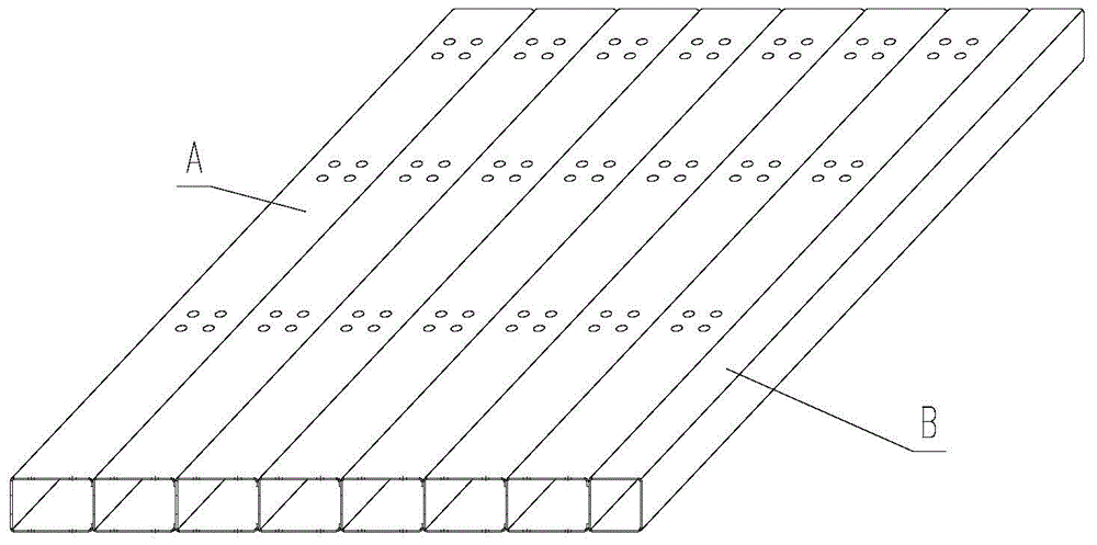
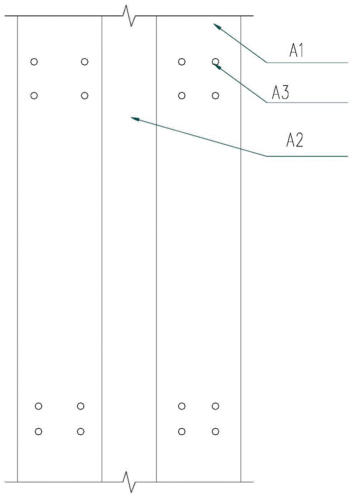
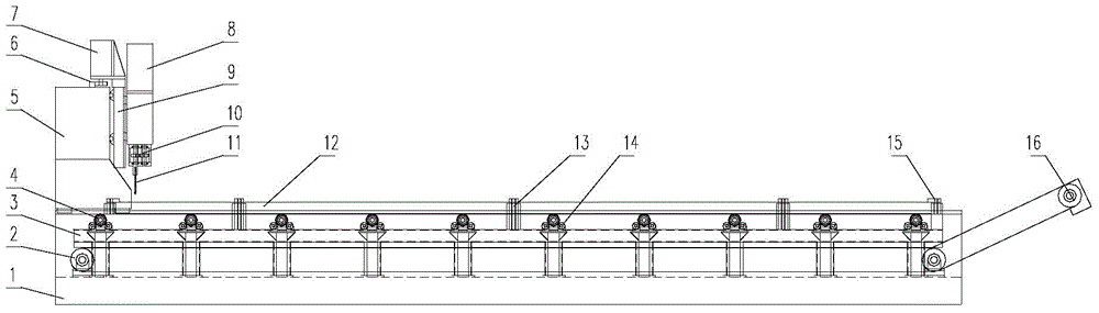
[0045] refer to Figure 1a to Figure 6b , CNC processing equipment for steel tube beam flange holes, including a supporting base 1, along the length direction of the base 1, a number of conveying rollers 4 are arranged in parallel, and several of the conveying rollers 4 are used to form a steel pipe A workbench for beam member 12 processing;

[0046] The base 1 is provided with a gantry frame 5 that can move along the length direction of the base and is used to install several drilling power heads. The drilling power head 8 can move horizontally along the gantry frame 5 Move; the bottom of the drilling power head 8 is equipped with a drill bit 11 for machining the holes of steel pipe bundle components.

[0047] A horizontal slide 9 is installed on the gantry frame 5, and the horizontal slide 9 is installed on the gantry frame 5 through a rolling linear guide pair, and a lateral movement motor is installed on the top of the horizontal slide 9 7. The horizontal sliding plate 9...


PUM


Abstract

The invention discloses a numerical control machining device for a steel pipe bundle flange hole. The numerical control machining device comprises a base playing a bearing role, and a plurality of conveying rollers arranged in the length direction of the base in parallel and used for forming a worktable for machining a steel pipe bundle component. The base is provided with a gantry rack which can move in the length direction of the base and is used for installing a plurality of drilling power heads, and the drilling power heads move in the transverse direction of the gantry rack through a gear and rack transmission pair. Drill bits used for a cutter for machining steel pipe bundle component holes are arranged at the bottoms of the drilling power heads. The steel pipe bundle flange drilling work is automatic, and the labor intensity of production workers is relieved while the product quality and the production efficiency are guaranteed.

Description

technical field [0001] The invention relates to a numerical control processing device for the hole of the flange plate of a steel pipe bundle. Background technique [0002] The I-shaped steel pipe bundle member is a new type of steel structure wall member, which is composed of several thin-walled U-shaped steel pipes and a square steel pipe of equal width used to seal the opening of the U-shaped steel pipe, which are stacked and welded together. Steel tube bundle member. Among them, the shape and structure of the I-type steel pipe bundle members are shown in Figure 1a As shown, the structure of the U-shaped steel pipe is shown in Figure 1b As shown, A is the cold-formed U-shaped steel pipe, B is the square steel pipe, A1 is the flange of the U-shaped steel pipe, A2 is the web, and A3 is the plate hole. On the wing plates of the U-shaped steel pipes forming the steel pipe bundle, there are arranged a group of small holes for interspersing steel bars in the construction of...

Claims


Application Information

Patent Timeline
Patent Type & Authority Applications(China)
IPC IPC(8): B23B39/16B23Q1/01B23Q7/05B23Q11/00B23Q3/06
CPCB23B39/162B23Q1/012B23Q3/062B23Q7/05B23Q11/0057
Inventor 贾宝英程凯
Owner HANGXIAO STEEL STRUCTURE
Why Eureka
Try Eureka