Device and method for adjusting laser spot size and target positioning

A laser spot and target material technology, which is applied in laser welding equipment, welding equipment, metal processing equipment, etc., can solve the problems of large instrument influence, low work efficiency, and limited adjustment range, etc. Convenience and clear measurement principle

Active Publication Date: 2016-05-11
WENZHOU UNIV
View PDF10 Cites 0 Cited by
  • Summary
  • Abstract
  • Description
  • Claims
  • Application Information

AI Technical Summary

Problems solved by technology

For example, patent CN103411534 discloses a method and device for measuring the spot size, which improves the knife-edge method and simplifies the adjustment of the optical path during spot measurement, but the operation is cumbersome and the instrument is greatly affected by the environment
Patent CN102670304 discloses a long-pulse laser spot size adjustment method and device, which uses a lens switching drum with several lens through holes to measure and adjust the spot size, but this patent is realized by controlling lenses with different focal lengths in the lens through holes Yes, with special features, not wide applicability
Patent CN103676159 discloses an optical path system that improves the shape of the spot and automatically adjusts the spot size. Devices such as microlens arrays, aspheric mirrors, and spatial filter holes are used to adjust the spot size. However, the adjustment range of this patent is not wide, and there are many additional devices. Overall work efficiency is not high
In the current experiment, the positioning method of the target generally adopts the form of splitting light to form visible light positioning or directly installs He-Ne laser, and uses small energy visible light to act on the spot, but this method has disadvantages, such as visible light has a certain spot size, which leads to poor positioning. inaccurate positioning

Method used


Image

  • Device and method for adjusting laser spot size and target positioning
  • Device and method for adjusting laser spot size and target positioning

Examples


Embodiment Construction

[0027] The invention utilizes the photo paper and the film covered on the photo paper to realize the function of adjusting the light spot and the positioning of the target, and the operation is simple and the cost is low.

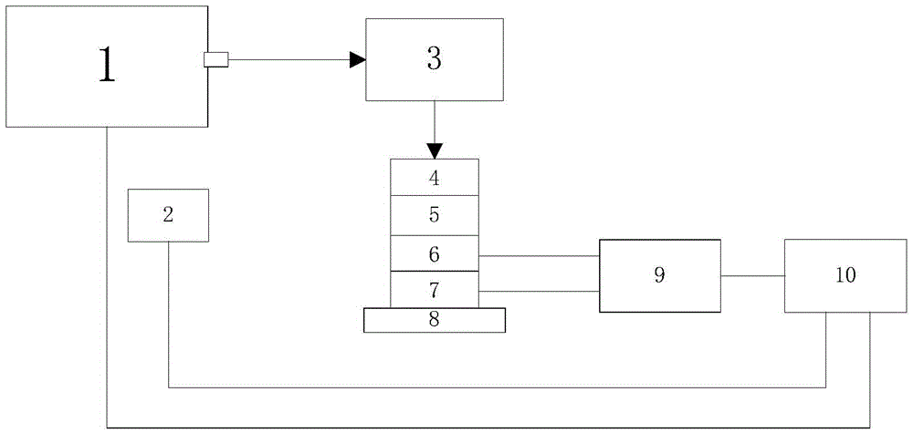
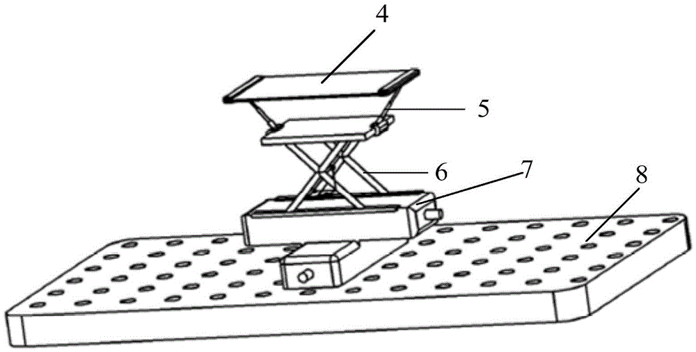
[0028] Such as figure 1 , figure 2 As shown, the device for adjusting laser spot size and target positioning includes laser 1, photoelectric sensor 2, optical path system 3, photographic paper 4, fixture 5, lifting table 6, X-Y motion table 7, multi-threaded hole base 8, servo The motor 9 and the industrial computer 10, the laser 1 is a pulsed laser, the laser parameters can be set by the industrial computer, and connected to the industrial computer 10, the clamp 5 for clamping the photo paper 4 is placed on the lifting platform 6, and the lifting platform 6 is installed on the X-Y On the motion table 7, the X-Y motion table 7 is located on the base 8 of the multi-thread hole table, the servo motor 9 is driven and connected to the X-Y motion table 8 and t...


PUM


Abstract

The invention relates to a device and method for adjusting laser light spot size and positioning target materials. A clamp used for clamping a piece of photographic paper is placed on a lifting platform, the lifting platform is mounted on an X-Y motion workbench, the X-Y motion workbench is positioned at the base of a multi-threaded hole workbench, a servo motor is in driving connection with the X-Y motion workbench and the lifting platform, a light path system is arranged on the output optical path of an optical laser, the output end of the light path system is arranged directly facing the photographic paper clamped by the clamp, a photoelectric sensor used for receiving optical signals is further arranged at the optical path output end of the optical laser, the photoelectric sensor is connected to an industrial computer, and the industrial computer is in control connection with the servo motor. Dispersed spots are formed on the photographic paper by using the effect of laser shock waves, so that precision measurement is performed, and approximating to required light spot size is achieved step by step; a thin film is used for positioning target materials; dimensions of the dispersed spots measured are used for approximating the required spot sizes.

Description

technical field [0001] The invention relates to a device and method for adjusting laser spot size and target positioning, which are used for various pulse lasers to determine the spot size and target positioning of various thicknesses and shapes. Background technique [0002] Spot size or diameter is an important parameter in laser processing. There are generally trepanning method, knife-edge method, and CCD method for the measurement of laser spot. These methods all specify the measurement methods in the national military standard GJB5441-2005. However, in practical applications, these methods have many defects. The trepanning method is mainly aimed at the spot that is circular or can predict the general shape in advance and the light field is symmetrically distributed, which is greatly limited in use. The knife-edge method has a strong ability to adapt to the shape of the spot, but the adjustment of the optical path is more complicated and the test accuracy is not high....

Claims


Application Information

Patent Timeline
Patent Type & Authority Patents(China)
IPC IPC(8): B23K26/073
CPCB23K26/073
Inventor 冯爱新薛伟印成李峰平张津超陆金花张健朱德华曹宇瞿建武
Owner WENZHOU UNIV
Why Eureka
Try Eureka