Method and system for three-dimensional positioning

A technology for 3D positioning and locating objects, applied in the field of 3D positioning, can solve the problems of high cost and difficult promotion, and achieve the effect of low cost and good immersion

Active Publication Date: 2016-07-27
赵锦秋
View PDF7 Cites 7 Cited by
  • Summary
  • Abstract
  • Description
  • Claims
  • Application Information

AI Technical Summary

Problems solved by technology

However, although the use of existing infrared positioning and laser positioning technologies can meet the requirements of virtual reality technology in terms of positioning speed and accuracy, the cost of implementing these technologies is too high to be popularized

Method used


Image

  • Method and system for three-dimensional positioning
  • Method and system for three-dimensional positioning
  • Method and system for three-dimensional positioning

Examples


Embodiment approach 1

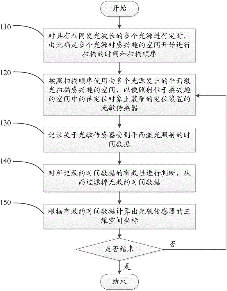
[0056] The first embodiment of the present application provides a three-dimensional positioning method for three-dimensional positioning of an object to be positioned in a space of interest, wherein the three-dimensional space coordinates and direction of the object to be positioned pass through a positioning device assembled on the object to be positioned The three-dimensional space coordinates of the photosensitive sensor to reflect. Specifically, the implementation flow diagram of the three-dimensional positioning method provided in Embodiment 1 is as follows: figure 1 As shown, including the following steps:

[0057] Step 110, to have the same emission wavelength λ 0 Multiple light sources Q 1 …Q m Time to check the time to determine multiple light sources Q 1 …Q m Scan time and scan sequence of the space of interest;

[0058] Step 120, using multiple light sources Q according to the scanning order 1 …Q m Plane laser L 1 …L m Scan the space of interest to illuminate the photos...

Embodiment approach 2

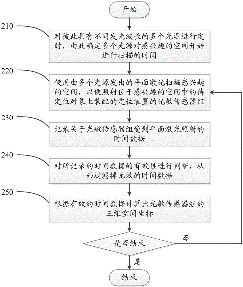
[0081] Embodiment 2 of the present application also provides a three-dimensional positioning method for performing three-dimensional positioning of an object to be positioned in a space of interest, wherein the three-dimensional space coordinates and direction of the object to be positioned are determined by the assembly on the object to be positioned. N photosensitive sensor groups of the device (S 11 …S 1m ), (S 21 …S 2m )...(S n1 …S nm ) To reflect the three-dimensional space coordinates, and one of the photosensitive sensor groups (S i1 …S im ) Includes multiple (e.g. m) photosensitive sensors installed together S i1 , S i2 …S im (Where i is an integer between 1 and m) is used to respond to multiple lasers with different wavelengths. Specifically, the implementation flow diagram of the three-dimensional positioning method provided in Embodiment 2 is as follows: image 3 As shown, including the following steps:

[0082] Step 210, the pairs have different emission wavelengths...

Embodiment approach 3

[0093] Embodiment 3 of the present application provides a three-dimensional positioning system for performing three-dimensional positioning of an object to be positioned in a space of interest, wherein the three-dimensional space coordinates and direction of the object to be positioned pass a photosensitive sensor assembled on the object to be positioned The three-dimensional space coordinates to reflect. Specifically, the three-dimensional positioning system provided in the third embodiment is such as Figure 4 As shown, the three-dimensional positioning system includes:

[0094] Multiple laser base stations P 1 …P m , The laser light it emits has the same emission wavelength λ 0 , Each of the multiple laser base stations has a timing control module, a planar laser source and a rotating device,

[0095] The timing control module receives the timing signal and controls the start time and sequence of the rotating device according to the timing signal,

[0096] The planar laser source...


PUM


Abstract

The invention discloses a method for three-dimensional positioning. The method is used for performing three-dimensional positioning on a to-be-positioned object in an interested space, and three-dimensional space coordinates and the direction of the to-be-positioned object are reflected through three-dimensional space coordinates of a photosensitive sensor of a positioning device assembled on the to-be-positioned object. The method comprises a step a) of performing timing on a plurality of light sources having the same emission wavelength, and determining the time and sequence of scanning an interested space by the light sources; a step b) of using plane laser to scan the interested space according to the scanning sequence, so as to irradiate the photosensitive sensor located in the interested space; a step c) of recording time data of the photosensitive sensor subject to plane laser irradiation; a step d) of judging validity of the recorded time data; a step e) of calculating the three-dimensional space coordinates of the photosensitive sensor according to the valid time data; and repeatedly executing the steps b) to e) until the execution of the method is stopped. Moreover, the invention further discloses a system for three-dimensional positioning.

Description

Technical field [0001] This application relates to the field of three-dimensional positioning, and specifically to a three-dimensional positioning method and system. Background technique [0002] In recent years, as one of the important forms of the next generation of human-computer interaction experience, virtual reality technology (VR: Virtual Reality, also known as the spiritual environment technology) has received more and more attention. The principle of virtual reality technology is to use computing devices to simulate a complete virtual three-dimensional world, so as to provide users with visual, auditory, tactile and other sensory simulations, allowing users to get an immersive experience and be able to The events and scenes that occur / appear in the virtual three-dimensional world interact in real-time without barriers. [0003] With the continuous improvement and advancement of virtual reality technology, users have higher and higher requirements for the authenticity of v...

Claims


Application Information

Patent Timeline
Patent Type & Authority Applications(China)
IPC IPC(8): G01S5/16
CPCG01S5/16
Inventor 赵锦秋胡全生
Owner 赵锦秋
Why Eureka
Try Eureka