Automatic mold adjusting method and tyre vulcanizer

An automatic adjustment and curing machine technology, applied to tires, other household appliances, household appliances, etc., can solve the problems of increasing the overall curing time of the tire, increasing the pre-vulcanization preparation work, reducing the production efficiency, etc., to save the mold change operation time, The effect of reducing die change process steps and improving production efficiency

Active Publication Date: 2015-09-02
HIMILE MECHANICAL SCI & TECH (SHANDONG) CO LTD
View PDF4 Cites 9 Cited by
  • Summary
  • Abstract
  • Description
  • Claims
  • Application Information

AI Technical Summary

Problems solved by technology

Since the backing plate is a steel plate, and the number of backing plates is large, manual operation has low safety and heavy workload, which incr

Method used


Image

  • Automatic mold adjusting method and tyre vulcanizer
  • Automatic mold adjusting method and tyre vulcanizer
  • Automatic mold adjusting method and tyre vulcanizer

Examples


Embodiment 1

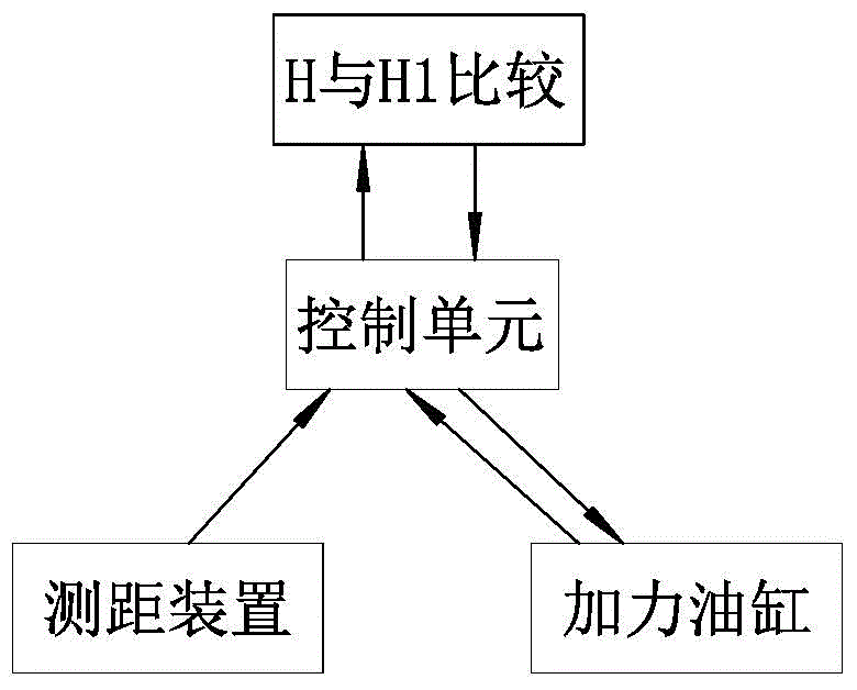
[0031] Such as Figure 1 to Figure 6 Commonly shown, the present invention provides a kind of automatic mold adjustment method, under the mold adjustment state, comprises the following steps: (a) set standard mold height value H in the control unit of vulcanizer, this standard mold height value H is The distance from a fixed height position on the vulcanizing machine to the upper side plate of the standard mold; (b) replace the tire and change the mold; (c) measure the actual height value H1 from the fixed height position to the upper side plate of the replaced tire mold, and compare the actual The height value H1 is transmitted to the control unit; (d) H1 is compared with H, the control unit drives the afterburner cylinder to drive the tire mold to move, and the moving distance ΔH=|H-H1|, where |H-H1| is the height of H and H1 The absolute value of the value difference, if H1>H, then the piston rod of the afterburner cylinder will be stretched out, and the tire mold will be m...

Embodiment 2

[0036] Such as Figure 1 to Figure 6 Commonly shown, the present invention provides an automatic mold adjustment method, which is basically the same as Embodiment 1, the difference is that a blind hole 305 is provided on the piston rod 303 of the booster cylinder 3, and the blind hole 305 is located at the bottom of the booster cylinder 3 On one side of the rodless cavity, the displacement sensor 307 is installed on the cylinder body 301 of the booster cylinder 3 and extends into the blind hole 305. The piston rod 303 of the booster cylinder 3 is provided with an induction ring 304, and the induction ring 304 and the displacement sensor 307 The displacement sensor 307 can sense the position of the piston rod 303 accurately. In order to improve the measurement accuracy of the displacement sensor 307 and prevent the interference caused by the flow of hydraulic oil, the piston rod 303 of the booster cylinder 3 is provided with an extension 306, and the extension 306 is slidably i...

Embodiment 3

[0038] Such as Figure 1 to Figure 6 As shown together, the present invention also provides a tire vulcanizing machine, which uses the automatic mold adjustment method in the above-mentioned embodiment 1 or embodiment 2.

[0039] Take the upper cover translational vulcanizing machine as an example to introduce the working principle of the automatic mold adjustment device:

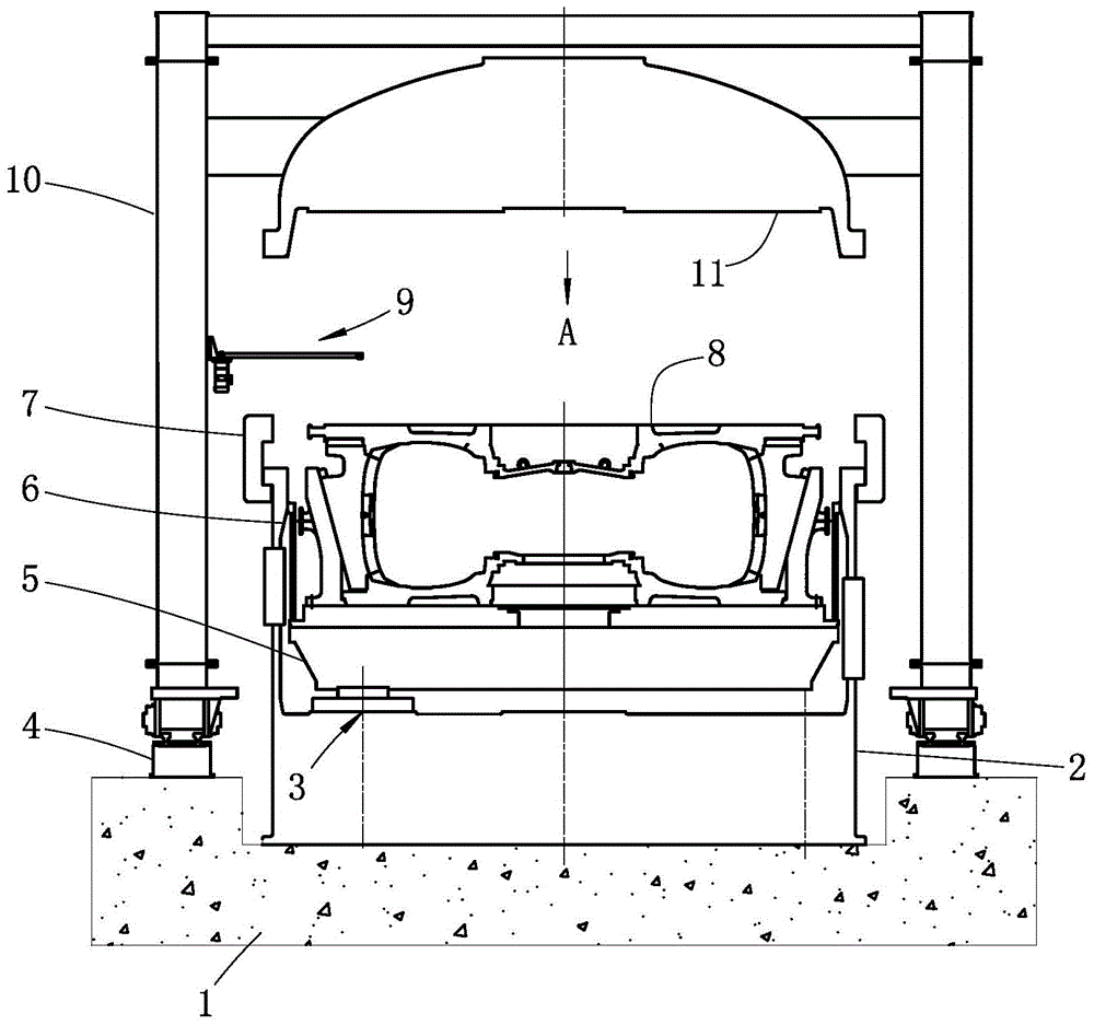
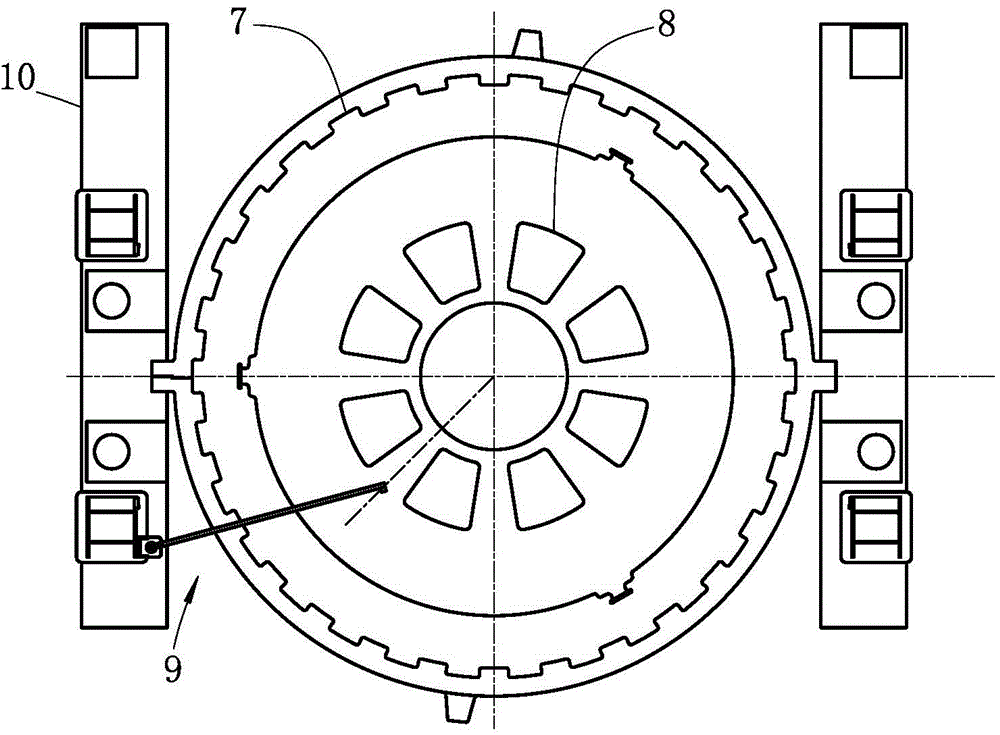
[0040] The main components of the tire vulcanizing machine are: a base 2 installed on the foundation 1, on both sides of the base 2 on the foundation 1 there are slide rails 4, and a frame 10 driven by a hydraulic cylinder is slidably installed on the slide rails 4, The frame 10 is generally a gantry structure and moves in parallel on the slide rails 4. The frame 10 is provided with an upper cover 11 driven by a lifting mechanism. The lifting mechanism usually uses a hydraulic cylinder. A steam chamber 6 is arranged above the base 2, and the steam A support plate 5 is slidingly installed in the chamber 6, ...


PUM


Abstract

The invention discloses an automatic mold adjusting method, belonging to the technical field of tyre vulcanizers. Under a mold adjusting state, the automatic mold adjusting method comprises the following steps: (a) setting a standard mold height value H in a control unit of the vulcanizer, wherein the standard mold height value H is a distance between a fixed height position on the vulcanizer and an upper side plate of a standard mold; (b) replacing a tyre mold; (c) measuring an actual height value H1 from a fixed height position to an upper side plate of the replaced tyre mold, and transmitting the actual height value H1 into the control unit; (d) comprising H1 and H, driving a driving cylinder to drive the tyre mold to move by means of the control unit, wherein the movement distance delta H is equal to absolute (H-H1). According to the automatic mold adjusting method, the height adjustment of the mold can be automatically finished after the tyre mold is replaced, the labor intensity of operation workers is lightened, the mold replacement operation time is saved, the automation degree is improved and the production efficiency is improved; the automatic mold adjusting method is widely applied to the adjustment of the tyre mold in the vulcanizer.

Description

technical field [0001] The invention relates to the technical field of tire vulcanizing machines, in particular to an automatic mold adjustment method and a tire vulcanizer using the automatic mold adjustment method. Background technique [0002] In the tire factory, a type of vulcanizing machine is often used to vulcanize tires of various specifications, but there is a certain gap in the diameter and thickness of tires of different specifications, and there is also a certain gap in the dimensions of the tire molds used. Therefore, it is necessary to adjust the position of the relevant parts of the vulcanizer to meet the height difference caused by the different dimensions of the tire mold. [0003] At present, the stroke of the afterburner cylinder of the vulcanizing machine produced by most manufacturers is small, which cannot meet the change range of the mold height when changing the mold. The adjustment method adopted by most people is to add or withdraw the contour cush...

Claims


Application Information

Patent Timeline
IPC IPC(8): B29C35/00B29C33/30B29L30/00
Inventor 曹世良陈世伟隋鹏李乐昌
Owner HIMILE MECHANICAL SCI & TECH (SHANDONG) CO LTD
Why Eureka
Try Eureka