Crane underframe

A crane and underframe technology, applied in the field of cranes, can solve the problems of high cost of automobile cranes, unsuitable for long-term use, etc., and achieve the effects of compact structure, low construction site requirements, and flexible operation.

Inactive Publication Date: 2015-09-02
SHANDONG JIANZHU UNIV
View PDF7 Cites 1 Cited by
  • Summary
  • Abstract
  • Description
  • Claims
  • Application Information

AI Technical Summary

Problems solved by technology

If it is considered to use a truck crane to complete the unloading and laying of prefabricated blocks, the truck crane has a high degree of freedom, flexible operation, and fast hoisting speed, but its requirements on the construction site are also very strict. In addition, the truck crane is expensive and generally not suitable for long-term use

Method used


Image

  • Crane underframe
  • Crane underframe
  • Crane underframe

Examples


Embodiment Construction

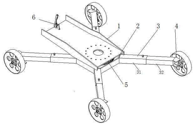
[0017] like figure 1 As shown, the crane underframe of the present invention includes a turntable 1, a base 2, a slewing bearing 5 installed between the turntable 1 and the base 2, a support leg 3 fixed on the base 2, and a support leg 3 installed at the end of the support leg 3. The walking wheel 4 and the slewing bearing 5 have an inner ring and an outer ring with teeth. The slewing table 1 can rotate freely relative to the base 2 around the slewing bearing 5. The bottom frame can move with the support legs 3 and the walking wheel 4 to realize the change of the position of lifting heavy objects. .

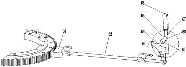
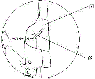
[0018] like figure 2 , image 3 As shown, the rotary locking mechanism 6 on the chassis is composed of a U-shaped fork 61, a lever 62, a locking handle 67 and a limit stop 63. The U-shaped fork 61 is fixedly connected to one end of the lever 62, and the lever 62 The other end is connected with the locking handle 67 by a rotating pair, the lever 62 is connected with the turnt...


PUM


Abstract

The invention discloses a crane underframe which comprises a revolving platform, a base, a revolving support which is arranged between the revolving platform and the base, supporting legs which are fixed on the base, and traveling wheels which are arranged on the end parts of the supporting legs, wherein the outer ring of the revolving support is provided with teeth; a revolving locking mechanism of the underframe comprises a U-shaped fork, a pull rod, a locking handle and a limiting blocking block; the revolving locking mechanism and the revolving platform can form a four-rod mechanism comprising a moving pair; the limiting blocking block is provided with ratchets; the locking handle is internally provided with a pressing rod, and pawls matched with the ratchets; each supporting leg is composed of a crossed beam and a stretching leg which are made from rectangular-section-type square pipes; the crossed beams are fixedly connected with the base; the stretching legs are connected with the crossed beams in an inserting manner and then are fixed by tightening bolts. The crane underframe is simple in structure, safe, reliable, high in environment adaptability and convenient to dismount, mount and transport.

Description

technical field [0001] The invention belongs to the technical field of cranes, and particularly relates to a crane underframe. Background technique [0002] Lifting operations are very common in construction. In order to achieve green construction, precast concrete blocks of a certain specification are often used for temporary roads and site laying on construction sites. The unloading and laying of the precast blocks also require lifting equipment. Commonly used tower cranes or mast cranes, etc. These lifting equipment are more efficient in repeated operations, but in order to ensure the safe operation of such equipment, the base needs a large area for reliable construction, and the terrain requirements of the construction site are It is also relatively strict, and the operation site is often relatively fixed, generally for long-term lifting operations and large lifting heavy objects. Obviously, the lifting of concrete precast blocks is not suitable for the above lifting equ...

Claims


Application Information

Patent Timeline
Patent Type & Authority Applications(China)
IPC IPC(8): B66C23/94B66C23/84B66C23/78
CPCB66C23/78B66C23/84B66C23/94B66C2700/00
Inventor 张明勤马荣全原政军苗冬梅姚玉善孟宪举王晴靳斐金钢韩立芳
Owner SHANDONG JIANZHU UNIV
Why Eureka
Try Eureka