A converter heat treatment parts cooling device

A converter heat treatment and cooling device technology, applied in heat treatment furnaces, heat treatment equipment, quenching devices, etc., can solve the problem of uneven hardness of workpieces, achieve the effects of improving quenching quality, reducing hardness dispersion, and preventing splashing

Active Publication Date: 2017-08-01
HANGZHOU ZIQIANG CHAIN DRIVE
View PDF7 Cites 0 Cited by
  • Summary
  • Abstract
  • Description
  • Claims
  • Application Information

AI Technical Summary

Problems solved by technology

[0003] In order to solve the above-mentioned technical problems, the purpose of the present invention is to provide a cooling device for heat treatment parts of the converter, which can effectively prevent problems such as quenching oil splashing, oily smoke in the workplace, and uneven hardness of workpieces after quenching.

Method used


Image

  • A converter heat treatment parts cooling device
  • A converter heat treatment parts cooling device
  • A converter heat treatment parts cooling device

Examples


Embodiment Construction

[0017] The specific implementation manner of the present invention will be described in detail below in conjunction with the accompanying drawings.

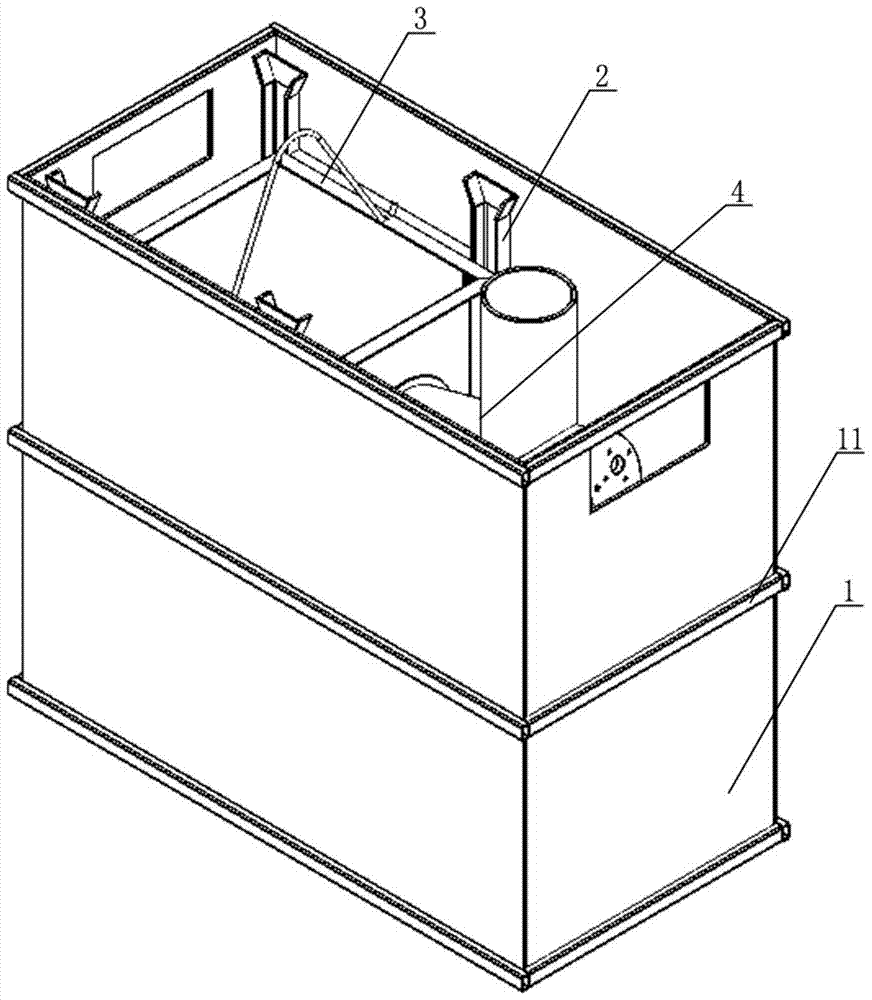
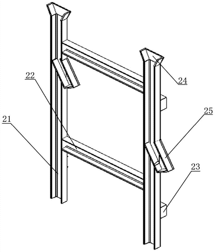
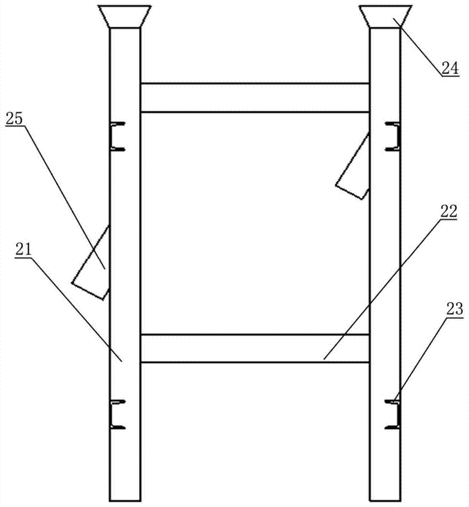
[0018] Such as figure 1 and Figure 5 The shown cooling device for heat treatment parts of a converter includes a converter, a cooling oil tank, a smoke exhaust pipe and a circulating oil circuit. At the same position on the two opposite inner walls of the fuel tank 1, the four side walls and the bottom of the basket 3 are all mesh plate structures, and one side wall of the basket 3 is provided with a through hole 31, and the basket 3 rests on the On the support 2, the guide pipe 4 includes a feed pipe 41 and an oil pipe 42 fixed to each other, one end of the oil pipe 42 is provided with a positioning sleeve 43, and the other end of the oil pipe 42 is provided with an end cover 44, and the oil pipe is provided with The angle between one end of the positioning sleeve 43 and the feed pipe 41 is 100°-110°, and the end of the oil p...


PUM


Abstract

The invention relates to a converter heat-treated part cooling device comprising a converter, a cooling oil tank, a smoke exhausting pipeline and a circulating oil way. The cooling oil tank comprises an oil tank, two supports, a lifting basket and a guide pipe; the supports are fixed to the same positions of the opposite inner walls of the oil tank respectively, four side walls and bottom of the lifting basket are in meshed sheet structures, one side wall of the lifting basket is provided with a through hole, and the lifting basket is placed on the supports; the guide pipes include a feed pipe and an oil pipe which are fixed mutually, one end of the oil pipe is provided with a positioning sleeve, the included angle between one end of the oil pipe provided with the positioning sleeve and the feed pipe ranges from 100 to 110 degrees, and the upper end of the feed pipe penetrates a fixed cover plate to connect to the part discharge port of the converter; the smoke exhausting pipeline is connected to the side wall of the oil tank in an inserted manner; the circulating oil way comprises two groups of oil pipelines and oil pumps. By the aid of the device, the rigidity difference of parts is reduced after quenching, and the part quenching quality is improved.

Description

technical field [0001] The invention relates to a cooling device for heat treatment parts, in particular to a cooling device for heat treatment parts of a converter. Background technique [0002] At present, in the heat treatment process of the chain, the oil-cooled quenching process after converter carburizing (or carbonitriding) is more commonly used for parts such as small-sized pin shafts that use low-carbon alloy steel. Conventional converters generally use an open oil tank, and the parts after heat preservation are directly poured into the quenching oil in the oil tank, and the oil tank is circulated or stirred at the same time. During this process, three problems are prone to occur: one is that a large amount of oil fume is produced during quenching, which permeates the workplace and endangers the health of workers; The discharged oil falls on the ground, causing a certain waste of quenching oil. At the same time, if it is not cleaned properly, the quenching oil wil...

Claims


Application Information

Patent Timeline
Patent Type & Authority Patents(China)
IPC IPC(8): C21D1/63C21D9/00
Inventor 宣碧华蒋锡林程华俊
Owner HANGZHOU ZIQIANG CHAIN DRIVE
Why Eureka
Try Eureka