
A cooling method for converter heat treatment parts

A converter heat treatment and cooling method technology, applied in heat treatment furnaces, heat treatment equipment, furnaces, etc., can solve the problems of quenching oil splashing and uneven hardness of workpieces, and achieve the effects of improving quenching quality and reducing hardness dispersion.

Active Publication Date: 2017-06-23
HANGZHOU ZIQIANG CHAIN DRIVE
View PDF6 Cites 0 Cited by
  • Summary
  • Abstract
  • Description
  • Claims
  • Application Information

AI Technical Summary

Problems solved by technology

[0003] In order to solve the above-mentioned technical problems, the object of the present invention is to provide a cooling method for heat-treated parts of the converter, which can effectively prevent problems such as splashing of quenching oil, diffuse oil smoke in the workplace, and uneven hardness of workpieces after quenching.

Method used


Image

  • A cooling method for converter heat treatment parts
  • A cooling method for converter heat treatment parts
  • A cooling method for converter heat treatment parts

Examples


Embodiment Construction

[0023] The specific embodiments of the present invention will be described in detail below in conjunction with the drawings.

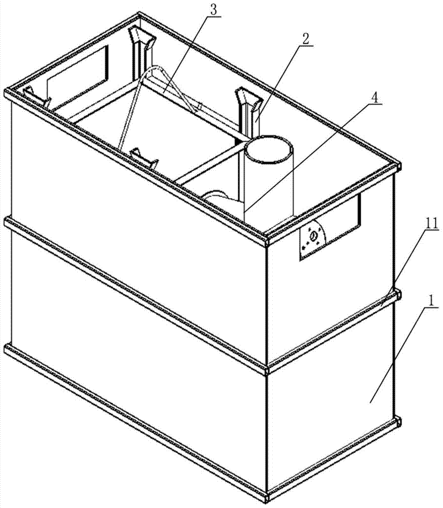
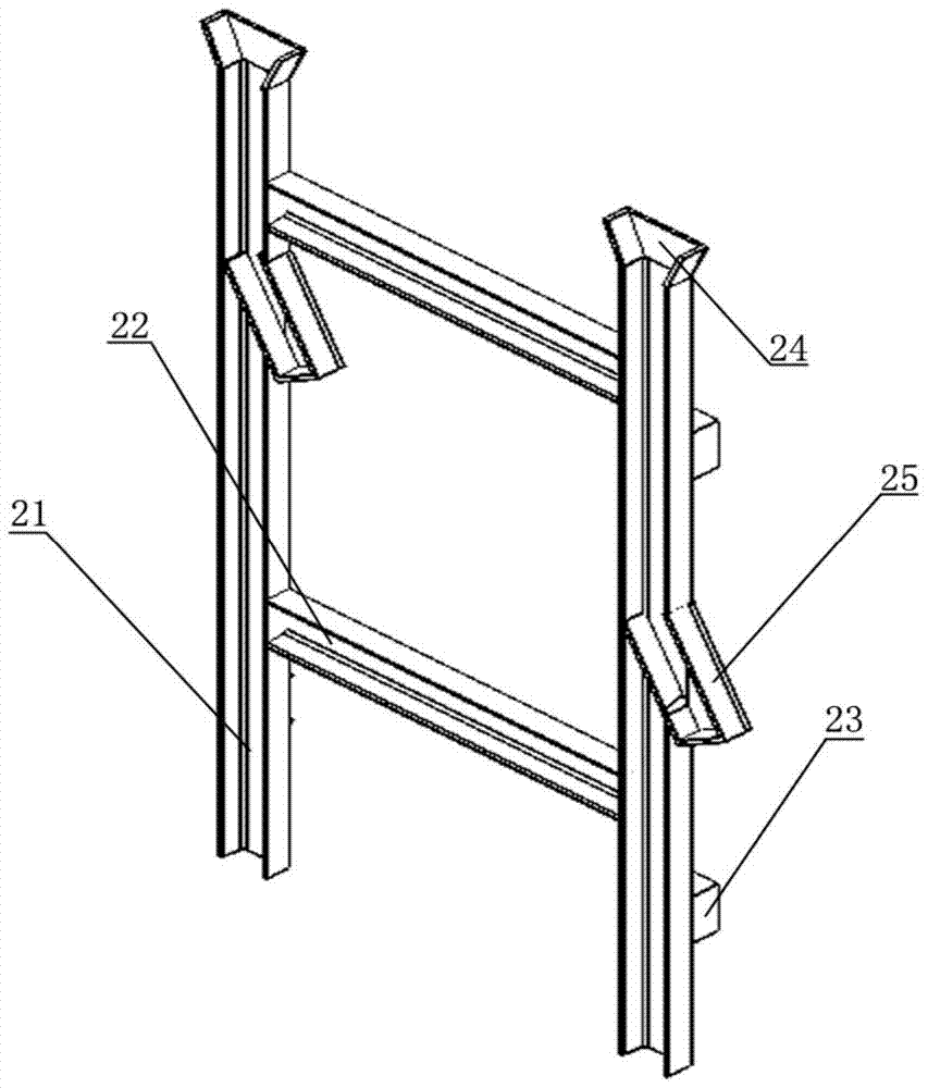
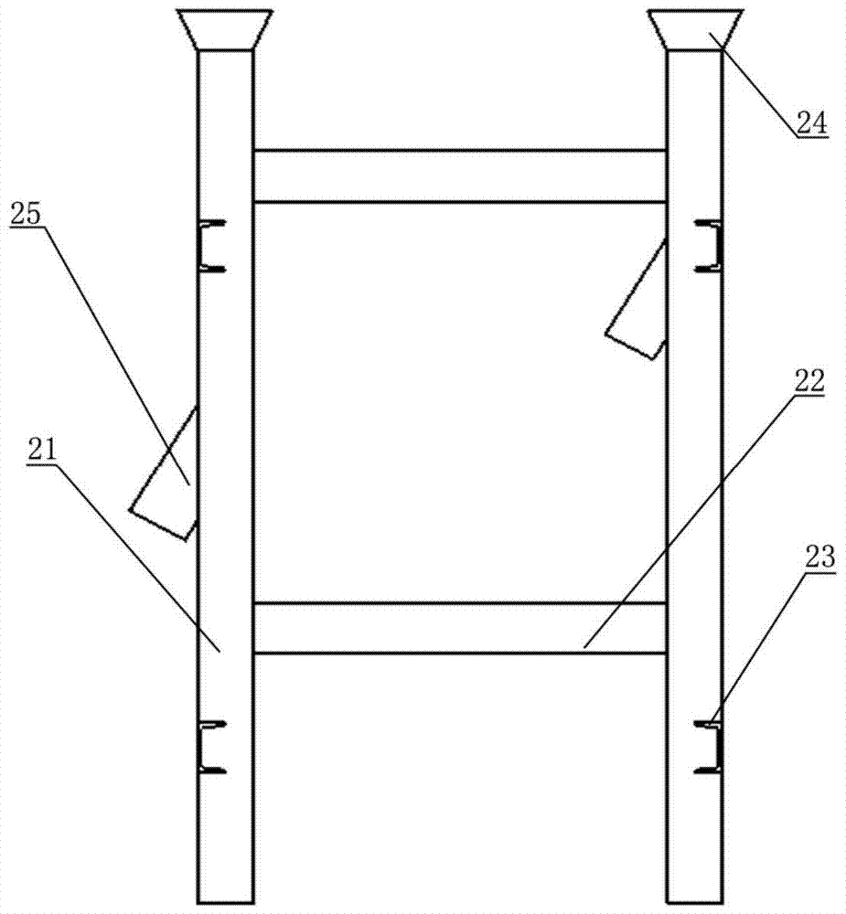
[0024] Such as figure 1 with Figure 5 A method for cooling heat treatment parts of a converter is shown. The equipment used includes a converter, a cooling oil tank, a smoke exhaust pipe and a circulating oil circuit. The cooling oil tank includes an oil tank 1, a bracket 2, a basket 3, and a draft tube 4, two The brackets 2 are respectively fixed at the same positions on the two opposite inner walls of the oil tank 1. The four side walls and the bottom of the basket 3 are all mesh plate structures, and one side wall of the basket 3 is provided with a through hole 31, The basket 3 rests on the bracket 2. The guide tube 4 includes a feed pipe 41 and an oil pipe 42 fixed to each other. One end of the oil pipe 42 is provided with a positioning sleeve 43, and the other end of the oil pipe 42 is provided with an end cover 44. The angle between one end of the...


PUM

PropertyMeasurementUnit
angleaaaaaaaaaa

Abstract

The invention relates to a cooling method for heat treatment parts of a converter. The equipment used includes a converter, a cooling oil tank, a smoke exhaust pipe and a circulating oil circuit. The cooling oil tank includes an oil tank, a bracket, a basket and a draft pipe. The processing steps include: a) parts Enter the converter for heat treatment. After the treatment is completed, the parts enter the feeding pipe from the outlet of the converter. b) The parts enter the feeding pipe. The flow rate of quenching oil is sent into the oil pipe, and the quenching oil completely submerges the parts and drives the parts to move to the basket; c) After the parts enter the basket continuously, the quenching oil flows out from the bottom and four walls of the basket and falls into the bottom of the oil tank, and then passes through the bottom of the oil tank The oil pipeline and the oil pump are sent back to the oil pipeline connected with the oil pipe end cover for recycling; the method adopted in the present invention can reduce the hardness dispersion of the parts after quenching and improve the quenching quality of the parts.

Description

Technical field [0001] The invention relates to a cooling method of heat-treated parts, in particular to a method for cooling heat-treated parts of a converter. Background technique [0002] At present, in the heat treatment process of chains, low-carbon alloy steel components such as small-size pins are more commonly used in converter carburization (or carbonitriding) followed by oil quenching. Conventional converters generally use an open oil tank, and the insulated parts are poured directly into the quenching oil in the oil tank while the oil tank is circulated or stirred. In this process, three problems are prone to occur: one is that a large amount of oily smoke is generated during quenching, which permeates the health of workers in the workplace; the other is that the open oil tank is used, and the quenching oil splashes and splashes when parts enter the oil tank. The discharged oil falls on the ground, causing a certain waste of quenching oil. At the same time, if the cl...

Claims


Application Information

Patent Timeline
Patent Type & Authority Patents(China)
IPC IPC(8): C21D1/63C21D9/00C21D1/18
Inventor 宣碧华蒋锡林程华俊
Owner HANGZHOU ZIQIANG CHAIN DRIVE
Learn More