Dust collector motor

A vacuum cleaner and sealing mechanism technology, which is applied in the field of high-efficiency vacuum cleaner motors, can solve problems such as reducing motor efficiency, and achieve the effect of improving energy efficiency

Inactive Publication Date: 2015-09-02
SUZHOU YONGJIE MOTOR
View PDF9 Cites 6 Cited by
  • Summary
  • Abstract
  • Description
  • Claims
  • Application Information

AI Technical Summary

Problems solved by technology

[0002] In order to avoid bad rubbing between the impeller cover and the moving impeller in the existing vacuum cleaner motor, the gap between the moving impeller and the impeller cover is reserved. The impeller cover does not need to undergo any processing when assembling, and it is directly pressed in, and the airflow in the impeller cover is easily sucked. It flows into the matching gap between the impeller cover and the moving impeller, thus forming useless work and reducing the efficiency of the motor. According to the size of the gap, its impact on the efficiency of the motor is also different. At present, the efficiency of traditional vacuum cleaner motors is generally around 40%.

Method used


Image

  • Dust collector motor
  • Dust collector motor

Examples


Embodiment Construction

[0015] The present invention will be described in detail below in conjunction with specific embodiments shown in the accompanying drawings. However, these embodiments do not limit the present invention, and any structural, method, or functional changes made by those skilled in the art according to these embodiments are included in the protection scope of the present invention.

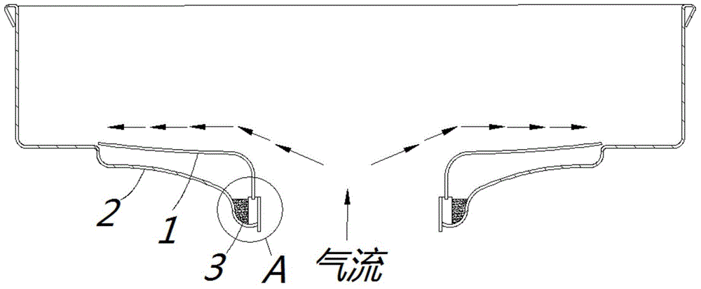
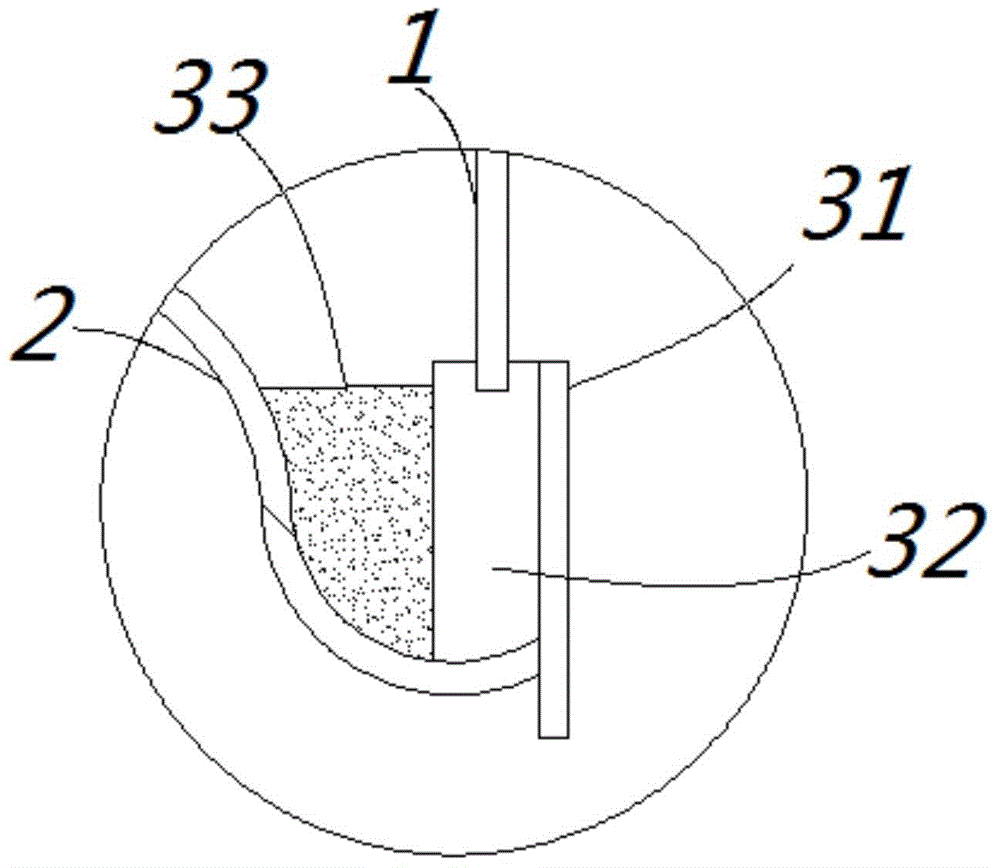
[0016] see Figures 1 to 2 , a vacuum cleaner motor, including a moving impeller 1 and an impeller cover 2, the air inlet of the impeller cover 2 is provided with a sealing mechanism 3 for eliminating the gap between it and the moving impeller 1, and the sealing mechanism 3 includes rubber Circle 31, paper circle 32 and silica gel 33 are filled.

[0017] The rubber ring 31 is fixedly connected to the edge of the air inlet and forms an annular recessed accommodation space with the inner wall of the impeller cover 2, and the paper ring 32 is fixedly arranged in the accommodation space. The upper end of...


PUM


Abstract

The invention discloses a dust collector motor. The dust collector motor comprises movable impeller and an impeller cover; a sealing mechanism is arranged at the air inlet of the impeller cover; the sealing mechanism comprises a supporting part and a connecting part; the supporting part is fixedly connected with the edge of the air inlet and combined with the inner wall of the impeller cover to form an annular concave receiving space; the connecting part is fixedly arranged in the receiving space; the end portion of the upper piece of the movable impeller is rotatably embedded into the connecting part. According to the dust collector motor, the sealing mechanism is arranged at the matching part of the impeller cover and the movable impeller, and airflow sucked into the impeller cover is not prone to flow into the matching gap between the impeller cover and the movable impeller, and therefore, the energy efficiency of the motor is greatly improved.

Description

technical field [0001] The invention relates to the technical field of vacuum cleaner manufacturing, in particular to a high-efficiency vacuum cleaner motor. Background technique [0002] In order to avoid bad rubbing between the impeller cover and the moving impeller in the existing vacuum cleaner motor, the gap between the moving impeller and the impeller cover is reserved. The impeller cover does not need to undergo any processing when assembling, and it is directly pressed in, and the airflow in the impeller cover is easily sucked. It flows into the matching gap between the impeller cover and the moving impeller, thus forming useless work and reducing the efficiency of the motor. According to the size of the gap, its impact on the efficiency of the motor is also different. At present, the efficiency of traditional vacuum cleaner motors is generally around 40%. . Contents of the invention [0003] The purpose of the present invention is to provide a vacuum cleaner moto...

Claims


Application Information

Patent Timeline
Patent Type & Authority Applications(China)
IPC IPC(8): F04D29/40F04D29/26A47L9/28
Inventor 林祖友邓邦强
Owner SUZHOU YONGJIE MOTOR
Why Eureka
Try Eureka