Check patentability & draft patents in minutes with Patsnap Eureka AI!

Human body head three dimensional scanner and three-dimensional modeling method

A head three-dimensional, scanner technology, applied in the field of human body scanning, can solve the problem of lack of three-dimensional equipment and modeling methods, and achieve the effect of high consistency, high speed and small error, and high photo quality

Inactive Publication Date: 2015-09-02
精迪测量技术(上海)有限公司
View PDF9 Cites 11 Cited by
  • Summary
  • Abstract
  • Description
  • Claims
  • Application Information

AI Technical Summary

Problems solved by technology

[0005] At present, there is no 3D equipment and modeling method that can automatically measure the human head on the market

Method used


Image

  • Human body head three dimensional scanner and three-dimensional modeling method
  • Human body head three dimensional scanner and three-dimensional modeling method

Examples


Embodiment 1

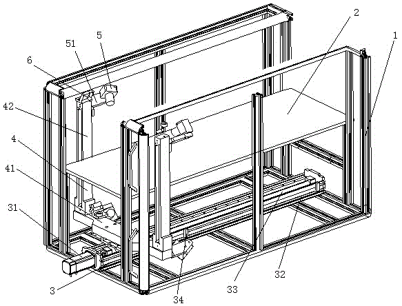
[0049] figure 1 It is a structural schematic diagram of the human body head three-dimensional scanner of the present invention, as figure 1As shown, the present invention provides a three-dimensional scanner for a human head and a three-dimensional modeling method, including: a frame 1, a glass plate 2, a driving device 3, a bracket 4, a camera 5 and a laser 6, and a glass plate 2, a driving device 3, The brackets 4 are all installed on the frame 1; the glass plate 2 is located above the driving device 3; the driving device 3 includes a servo drive motor 31, a slide rail 32, a screw rod 33 and a limit switch 34, and the slide rail 32 is installed on the frame 1. At the bottom, the limit switch 34 and the servo drive motor 31 are all installed on the slide rail 32, and the servo drive motor 31 is connected with the screw mandrel 33; the support 4 includes a crossbeam 41 and two columns 42, and the bottom of the crossbeam 41 is sleeved on the wire by a bearing. On the rod 33, t...

Embodiment 2

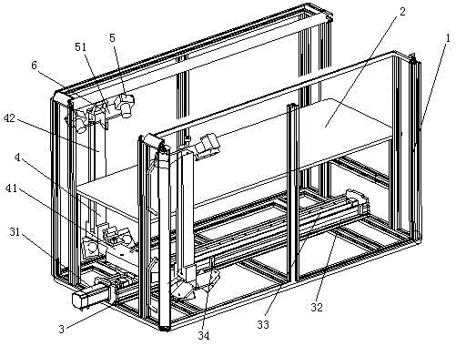
[0053] figure 2 It is the structure schematic diagram of embodiment 2 of human body head three-dimensional scanner embodiment 2, on the basis of embodiment 1, the quantity of word line laser 6 is 4 in the present embodiment, the quantity of CCD industrial camera 5 is 8, 2 One word-line laser 6 is located at the top of two columns 42 respectively, and the remaining two line lasers 6 and the two line lasers 6 at the top of the two columns 42 are symmetrical to the central axis and respectively located on the beam 41. The four CCD industrial The cameras 5 are respectively positioned at the tops of two columns 42 through the rotation shafts 51, and the remaining four CCD industrial cameras 5 are symmetrical to the central axis of the CCD industrial cameras 5 at the tops of the two columns 42, and are respectively positioned on the beam 41 through the rotation shafts 51; the CCD industrial cameras The quantity of 5 is 8, and the frame is square, hexagonal, rectangular or circular....


PUM


Abstract

The present invention relates to the human body scanning technology field, and provides a human body head three dimensional scanner and a three-dimensional modeling method. The human body head three dimensional scanner comprises a frame, a glass plate, a driving device, a support, cameras and lasers, the glass plate, the driving device and the support are arranged on the frame, and the glass plate is located above the driving device. The driving device comprises a servo driving motor, a slide rail, a leas screw and a limiting switch, the slide rail is arranged at the bottom of the frame, the limiting switch and the servo driving motor are arranged on the slide rail, and the servo driving motor is connected with the lead screw. The support comprises a crossbeam and two upright columns, the bottom of the crossbeam sleeves the lead screw via a bearing, and the upright columns are arranged at the two ends of the crossbeam. The three or more than three lasers are arranged on the two upright columns and the crossbeam, and the four or more than four cameras are arranged on the two upright columns and the crossbeam via rotating shafts and are connected with an external computer. The human body head three dimensional scanner and the three-dimensional modeling method of the present invention can measure the form and curve characteristics of a head, and have the advantages of being fast in measurement speed, small in error and little in workload, and being simple to install and accurate to measure.

Description

technical field [0001] The invention relates to the technical field of human body scanning, in particular to a three-dimensional scanner for a human head and a three-dimensional modeling method. Background technique [0002] From the perspective of technological development, anthropometric technology can be divided into traditional anthropometric technology and three-dimensional anthropometric technology. [0003] Traditional measurement technology uses soft ruler, human body altimeter, angle meter, distance meter, variable human body section measuring instrument, etc. as the main tools, which can directly measure the body surface length and cross-sectional shape of various parts of the human body, and the tools are simple , easy to operate, so it has been adopted in the garment industry for a long time. However, since these methods are all contact measurements, they often make the subject feel embarrassed or tired, or cause measurement errors due to the lack of skill of th...

Claims


Application Information

Patent Timeline
IPC IPC(8): G06T7/00
CPCG06T7/596G06T7/521G06T2207/10012G06T2207/20221G06T2207/30196
Inventor 汪小星
Owner 精迪测量技术(上海)有限公司
Features
  • R&D
  • Intellectual Property
  • Life Sciences
  • Materials
  • Tech Scout
  • Unparalleled Data Quality
  • Higher Quality Content
  • 60% Fewer Hallucinations
Learn More