Rotary operation time difference signal trigger mechanism and its isolating switch

A technology of signal triggering and rotating operation, applied in the direction of air switch parts, etc., can solve the problems of personal safety and safety hazards, and achieve the effect of simple design structure, strong designability, and strong trigger time difference.

Active Publication Date: 2017-06-30
SICHUAN HABOAT ELECTRIC CO LTD
View PDF5 Cites 0 Cited by
  • Summary
  • Abstract
  • Description
  • Claims
  • Application Information

AI Technical Summary

Problems solved by technology

The disadvantage of this connection method is that when the isolating switch inside the isolating switch box is disconnected and closed, the contactor controlled by the remote control cabinet is disconnected in advance and then closed synchronously. Personal safety poses a safety hazard

Method used


Image

  • Rotary operation time difference signal trigger mechanism and its isolating switch
  • Rotary operation time difference signal trigger mechanism and its isolating switch
  • Rotary operation time difference signal trigger mechanism and its isolating switch

Examples


Embodiment

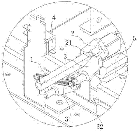
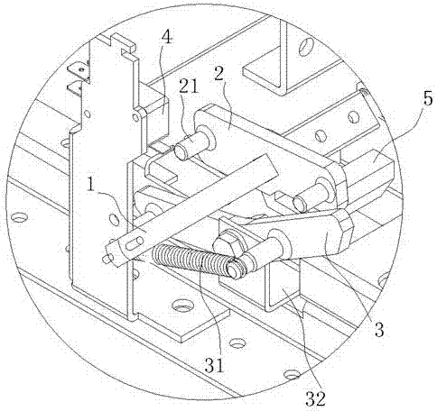
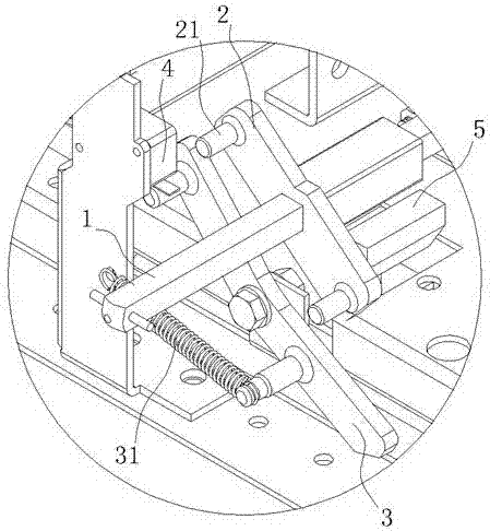
[0029] The rotating operation time difference signal trigger mechanism of the present invention includes a rotating shaft 1 , a toggle member 2 , a trigger member 3 and a trigger switch 4 , the toggle member 2 is driven by the rotating shaft 1 , and the trigger member 3 is within the rotation angle of the rotating shaft 1 . It has a first stroke that can be driven by the toggle member 2, the trigger member 3 also has a second stroke that can be triggered within the rotation angle of the rotating shaft 1, and the trigger switch 4 is arranged on the first stroke or the second stroke of the trigger member 3. Location. Meanwhile, the first stroke and the second stroke have a time difference. The rotating shaft 1 drives the toggle member 2, and the toggle member 2 drives the trigger member 3, and the specific driving form may be a motion form including rotation or displacement. The design principle of the present invention lies in that the first stroke and the second stroke have a...


PUM


Abstract

The invention discloses a rotation operation time difference signal trigger mechanism and an isolating switch thereof. The rotation operation time difference signal trigger mechanism comprises a rotating shaft, a pulling element, a trigger element, and a trigger switch. The pulling element is driven by the rotating shaft. The trigger element has a first stroke capable of being driven by the pulling element in rotation angles of the rotating shaft. The trigger element has a second stroke capable of being triggered in rotation angles of the rotating shaft. The trigger switch is arranged on position of the first stroke or the second stroke of the trigger element. The mechanism can realize triggering of time difference signals in rotation operation under design principle of two strokes of the trigger element and generation methods thereof. When the mechanism is used in the isolating switch, the mechanism provides triggering of auxiliary contact pre-breaking signals in on-off operation, and realizes a trigger controlled by a remote control cabinet receives signals of the trigger switch to realize nonsynchronous pre-breaking and post-closing when the isolating switch in a switch box is switched off and switched on, so as to ensure safe operation.

Description

technical field [0001] The invention relates to a mechanism capable of providing a time difference signal for rotary operation, in particular to a time difference signal trigger mechanism capable of providing auxiliary contact pre-breaking signals for an isolating switch, and an isolating switch using the time difference signal trigger mechanism for rotary operation. Background technique [0002] Taking the current connection scheme of the isolation switch box and the main body of the remote control cabinet as an example, the isolation switch and its own auxiliary switch are mainly used for direct connection with the control circuit, and the isolation switch and its own auxiliary switch are located in the isolation switch box. The disadvantage of this connection method is that when the isolation switch inside the isolation switch box is disconnected and closed, the contactor controlled by the remote control cabinet is simultaneously disconnected and closed in advance. Person...

Claims


Application Information

Patent Timeline
Patent Type & Authority Patents(China)
IPC IPC(8): H01H31/02
CPCH01H31/02
Inventor 叶建川杨孝洪王涛叶春志李明宏林聪
Owner SICHUAN HABOAT ELECTRIC CO LTD
Why Eureka
Try Eureka