

Balanced filter using improved coupling feed line
A balanced filter and an improved technology, applied in waveguide-type devices, electrical components, circuits, etc., can solve the problem of difficult control of the differential mode high-frequency stopband of the balanced filter, and achieve independent design, good characteristics and low cost. Effect
- Summary
- Abstract
- Description
- Claims
- Application Information
AI Technical Summary
Problems solved by technology
Method used
Image

Examples
Embodiment Construction
[0036] The present invention will be further described below in conjunction with specific examples.
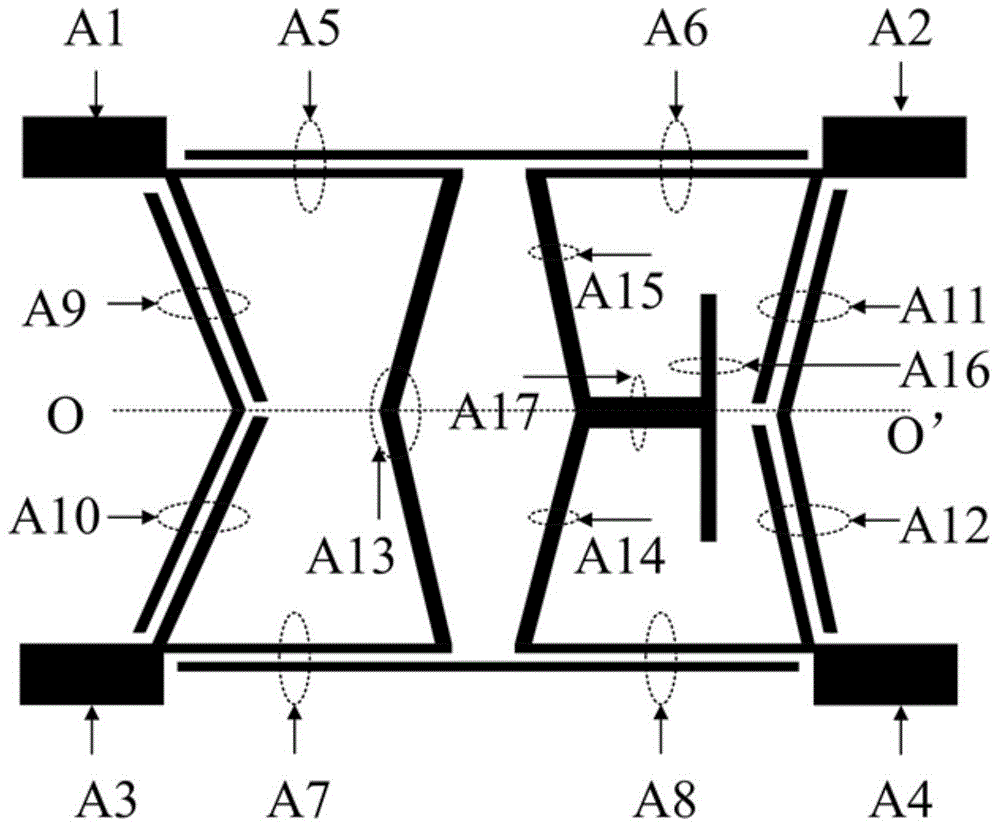
[0037] Such as figure 1 As shown, the balanced filter using the improved coupling feeder described in this embodiment includes input and output ports A1, A2, A3, A4 (transmission lines with impedance 50Ω), and two cascaded improved coupling feeders; wherein An improved coupled feeder line includes a first coupled transmission line A5 and a second coupled transmission line A7 distributed mirror-symmetrically with the horizontal central line 00' as a symmetrical axis, and a first coupled transmission line A5 and a second coupled transmission line A7 loaded between the first coupled transmission line A5 and the second coupled transmission line A7. A branch A13, the first branch A13 is formed by connecting two mirror-symmetrical transmission lines, and the two transmission lines are on the same axis of symmetry as the first coupling transmission line A5 and the second coupling tr...
PUM
 Abstract
Description
Claims
Application Information