Base station and user terminal multi-cell implement method and apparatus
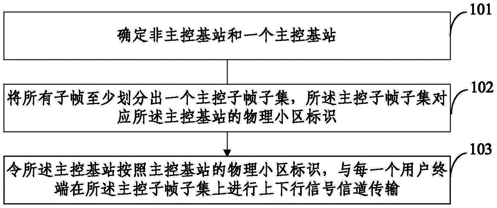
An implementation method and user terminal technology, applied in the field of multi-cell implementation of base stations and user terminals, can solve problems such as the reduction of UE data transmission efficiency, reduce the impact of system throughput and user experience, ensure continuous transmission, and avoid data transmission. rate reduction effect
- Summary
- Abstract
- Description
- Claims
- Application Information
AI Technical Summary
Problems solved by technology
Method used
Image
Examples
Embodiment 1
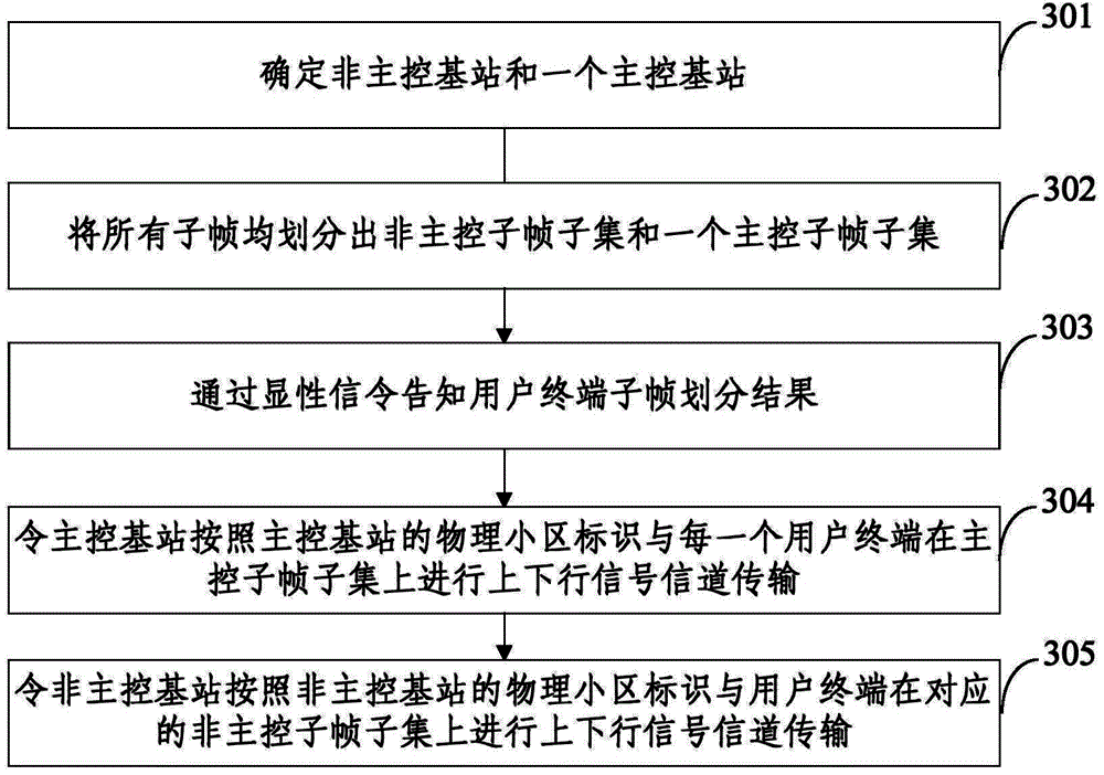
[0093] Embodiment 1 of the present invention is a method for realizing base station virtual multi-cell. For specific steps, see image 3 .
[0094] Step 301: Determine a non-master base station and a master base station.
[0095] In the embodiment of the present invention, the two adjacent cells A and B both work in TDD-LTE mode and have the same carrier frequency, and the cells A and B have different PCIs, that is, the respective PCIs are PCI-a, PCI-a, and PCI-a respectively. -b. First, a master base station is determined through information exchange between cell A and cell B. In this step, a virtual base station S is introduced as the master base station. The virtual base station S is set on cell A and cell B, and the PCI is PCI-s , PCI-s differs from both PCI-a and PCI-b, see Figure 4 , then cell A and cell B are both non-master base stations at this time.
[0096] In addition, the method of introducing the virtual base station S is not limited to the one in this embod...
Embodiment 2
[0109] Embodiment 2 of the present invention is a method for realizing multiple cells of a base station. For specific steps, see Figure 6 .
[0110] Step 601: Determine a non-master base station and a master base station.
[0111] In Embodiment 2 of the present invention, there are three cells: cell A, cell B, and cell S, all of which work in TDD-LTE mode and have the same carrier frequency, and the PCIs they have are respectively PCI-a, PCI-b, and PCI- s. First of all, through information exchange between the cells, it is determined that cell S is the master base station, and cell A and cell B are non-master base stations. See Figure 7 .
[0112] Step 602: Divide the subframes into master control subframe subsets.
[0113] In this step, all subframes in cell A, cell B, and cell S are Figure 5 The manner shown is divided into two subframe subsets, wherein firstly, the downlink subframe is divided into subsets, and then the uplink subframe is implicitly divided into sub...
Embodiment 3
[0124] Embodiment 3 of the present invention is a method for realizing virtual multi-cell of a user terminal. For specific steps, refer to Figure 8 .
[0125] Step 801: Receive the subframe subset division result of the base station, and divide all subframes into a non-main control subframe subset and a main control subframe subset.
[0126] In this step, the explicit signaling of the base station is received to obtain the subframe division result, and all subframes are divided according to Figure 5 The shown method is divided into two subframe subsets. In the embodiment of the present invention, the first subframe subset is composed of subframe #0 / 1 / 2 / 5 / 6 / 7 of each wireless frame, and PCI1 corresponds to PCI- a or PCI-b, the second subframe subset consists of subframe #3 / 4 / 8 / 9 of each radio frame, and PCI2 corresponds to PCI-s. Therefore, the first subframe subset is a non-main control subframe subset, corresponding to cell A or cell B, where the correspondence depends on...
PUM
 Abstract
Description
Claims
Application Information
 - R&D
- Intellectual Property
- Life Sciences
- Materials
- Tech Scout
- Unparalleled Data Quality
- Higher Quality Content
- 60% Fewer Hallucinations
Browse by: Latest US Patents, China's latest patents, Technical Efficacy Thesaurus, Application Domain, Technology Topic, Popular Technical Reports.
© 2025 PatSnap. All rights reserved.Legal|Privacy policy|Modern Slavery Act Transparency Statement|Sitemap|About US| Contact US: help@patsnap.com


