Slip handle labor saving lopper machine

A technology of high branch shears and sliding handle, applied in the field of high branch shears, can solve the problems of easily damaged pull rope, tripping damage, not compact, etc., and achieve the effect of convenient operation

Inactive Publication Date: 2015-09-09
CHENGDU UNIVERSITY OF TECHNOLOGY
View PDF21 Cites 5 Cited by
  • Summary
  • Abstract
  • Description
  • Claims
  • Application Information

AI Technical Summary

Problems solved by technology

But this design can only save 2 times the force, so it has to use the lever force-saving method to increase the shear force on the upper part, and the tension spring (return spring) is outside, which is not compact and easy to be damaged by tripping. Externally, pulleys and pull cords are prone to jamming by debris
In addition, the design of the drawstring passing through the narrow slit causes a lot of resistance and easy damage to the drawstring

Method used


Image

  • Slip handle labor saving lopper machine
  • Slip handle labor saving lopper machine
  • Slip handle labor saving lopper machine

Examples


Embodiment Construction

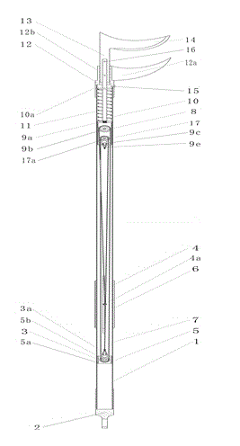
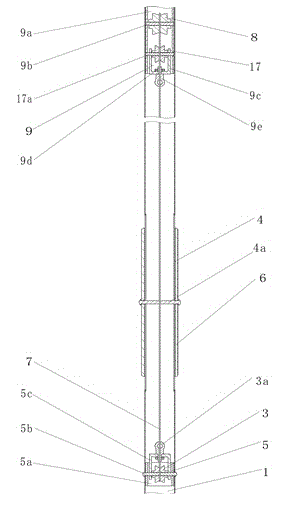
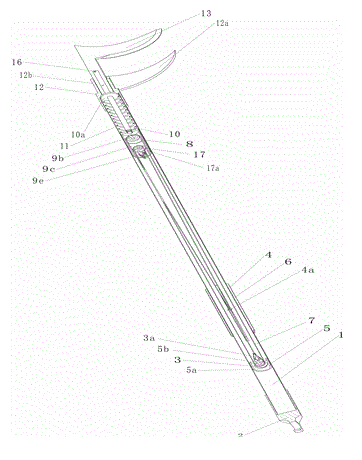
[0022] figure 1 , figure 2 , image 3 It is an embodiment of the labor-saving high-branch shears with a sliding handle. The grip bar 1 is a long tube, and one end of the grip bar 1 is provided with a hanging sleeve 18, and a screw hole is opened on the tube wall at the other end. A through hole passing through the axis is arranged on the grip bar 1 on the top of the groove 4 . The handle 2 is sleeved on the handle bar 1 for easy handling. The sliding handle 6 is a tubular part held by one hand, and a sliding handle pin rod 4a is radially connected to the two walls, and the sliding handle 6 is sleeved on the handle bar 1 . The transmission rod 10 is a rod-shaped member, and a stop plate 10a is arranged in the middle of the transmission rod 10 . The back-moving spring 11 is a stage clip that can be loaded into the grip bar 1 .

[0023] The pulley assembly includes movable pulley 8, small movable pulley 17, fixed pulley 3, fixed pulley mounting part 5, movable pulley moun...


PUM


Abstract

The invention discloses a slip handle labor saving lopper machine. The slip handle labor saving lopper machine is characterized in that a slide chute is arranged on a grip handle, a slip handle sleeves a grip rod, a pin rod passes through the slip handle in the radial direction, and is connected with the slip handle, movable pulleys and fixed pulleys are respectively installed on a movable pulley installation piece and a fixed pulley installation piece, the movable pulley installation piece can slide in the grip handle, the fixed pulley installation piece is fixedly connected in the grip rod, one end of a pulling rope is connected with an installation piece, the other end of the pulling rope is wound around the pulleys in sequence according to a spiral line mode, and then is connected with a slip handle pin rod, the pulleys are arranged in the axial direction of the grip rod, axles of the pulleys are parallel to one another, a baffle disc is arranged on a transmission bar, the inner end of the transmission bar is connected with the movable pulley installation piece, a reset spring sleeves the transmission bar, one end of the reset spring is pressed against the movable pulley installation piece, the other end of the reset spring is pressed against the baffle disc on the transmission bar, a connection head of a shear head sleeves the end of the grip handle, one end of the connection head is connected with a slide groove with a fixing tool, a slip sheet is connected with the slide groove in slip mode, the upper portion of the slip sheet is provided with a moving tool, and the lower portion of the slip sheet is connected with the transmission bar. A user pulls the slip handle, and the shear head is driven to work in labor saving mode. The slip handle labor saving lopper machine can select different labor saving multiples by selecting the number of the pulleys where the pulling rope is wound.

Description

technical field [0001] The invention relates to a garden pruning tool, in particular to a high-branch shears which can be cut by pulling a sliding handle. Background technique [0002] High branch shears are a widely used gardening pruning tool. Today's high pruning shears are also available in a variety of designs. Such as the Chinese patents whose publication numbers are CN201320501628, CN99104224, CN201320857176, CN98234861, but these designs are all to set the lever labor-saving device outside the bar of the high-branch shears, the one is to increase the length of the shear arm at the top, and the 2nd is to increase the length of the handle at the bottom, but this This kind of structure takes up a lot of space, and it is easy to trip the branches in the upper part, which will affect the use. The lower part requires a large operating space, and the direction of force application is inconsistent with the axis direction of the same rod, which affects the operation and cont...

Claims


Application Information

Patent Timeline
Patent Type & Authority Applications(China)
IPC IPC(8): A01G3/025
Inventor 杨勇张进武敏琪
Owner CHENGDU UNIVERSITY OF TECHNOLOGY
Why Eureka
Try Eureka