Full-membrane wall circulating fluidized bed boiler without corridor corner tube

A circulating fluidized bed and membrane wall technology, which is applied in water tube steam boilers, fluidized bed combustion equipment, boiler water pipes, etc. , increase the power consumption of the induced draft fan, etc., to achieve the effect of saving refractory materials, easy on-site installation, and good thermal insulation performance

Inactive Publication Date: 2011-12-07
XI AN JIAOTONG UNIV
View PDF0 Cites 2 Cited by
  • Summary
  • Abstract
  • Description
  • Claims
  • Application Information

AI Technical Summary

Problems solved by technology

The separator has a huge structure and needs a special steel frame to support it. It is generally arranged between the furnace and the convection heating surface to form a gallery. The structure is complicated, the floor area is large, and the consumption of raw materials is large;
[0010] 2. The water-cooled wall of the circulating fluidized bed boiler adopts a suspended membrane water-cooled wall structure. However, since the separator is arranged between the furnace and the convective heating surface, the corridor space in the middle of the separator separates the furnace and the convective heating surface. Separated, it is difficult to realize the sealing structure of the full-membrane wall, and the convection heating surface of circulating fluidized bed boilers with medium and lower capacity levels can only use supporting heavy-duty furnace walls;
[0011] 3. The structure of the high-temperature separator of the existing circulating fluidized bed boiler has a long transition section between the inlet and the outlet, the flue gas flow is extremely difficult, the flow resistance is large, and the power consumption of the induced draft fan is increased.
Circulating fluidized bed boilers require large infrastructure investment, large steel consumption, large power consumption, and large consumption of refractory materials, which have seriously delayed the development of medium and lower-capacity circulating fluidized bed boilers. It is necessary to invent a new type of circulating fluidized bed boiler. The fluidized bed boiler reduces infrastructure investment, reduces steel consumption, electricity consumption and refractory material consumption, enhances the technology and product competitiveness of circulating fluidized bed boilers, and enhances the confidence of heat and electricity users in choosing circulating fluidized bed boilers

Method used


Image

  • Full-membrane wall circulating fluidized bed boiler without corridor corner tube
  • Full-membrane wall circulating fluidized bed boiler without corridor corner tube
  • Full-membrane wall circulating fluidized bed boiler without corridor corner tube

Examples


Embodiment Construction

[0036] The structural principle and working principle of the present invention will be described in detail below in conjunction with the accompanying drawings.

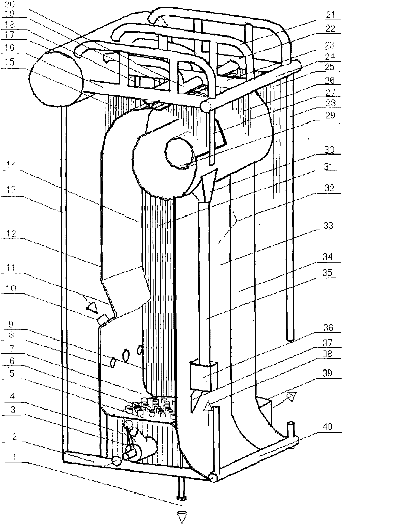
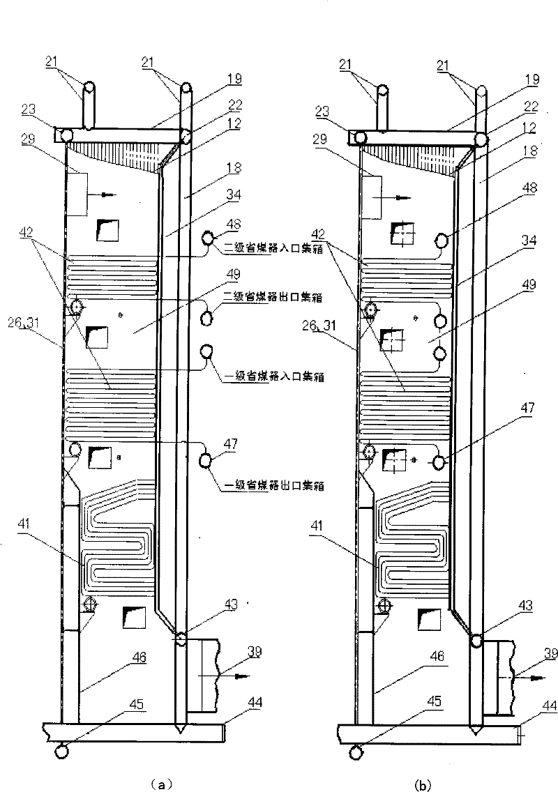
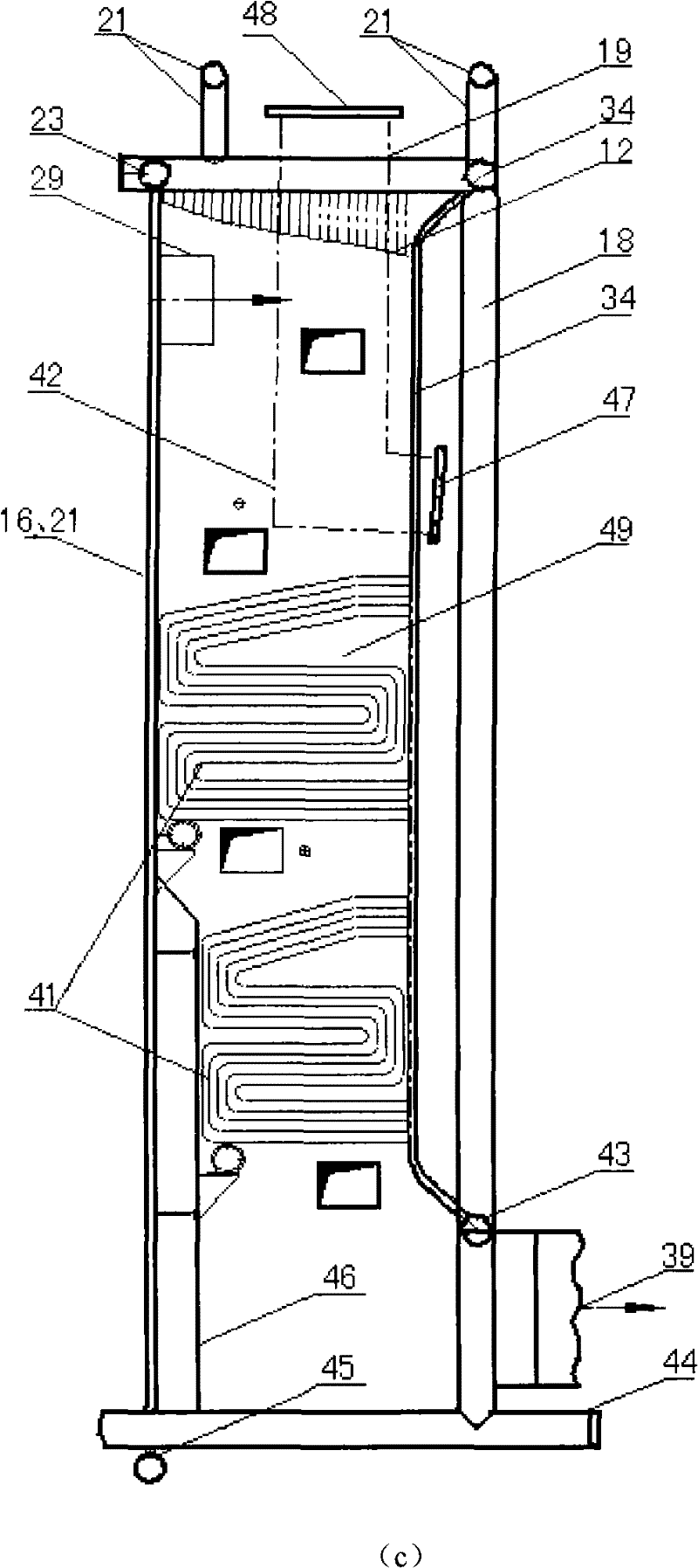
[0037] see figure 1 , figure 2 , the present invention includes the corner tubes 13, 18, 27, 28 arranged at the four corners of the boiler furnace, the lower headers 2, 40 at the bottom of the furnace and the upper headers 16, 19, 20, 22, 23, 24 at the top of the furnace, and the horizontal The frame-type self-supporting structure system composed of a single drum 17 is connected to the front wall membrane water wall 12 and the rear wall of the upper header 16, 19, 20, 22, 23, 24 and the lower header 2, 40 through corner joints. Wall membrane water cooling wall 32, left wall membrane water cooling wall 25, right wall membrane water cooling wall 15, double-sided exposure membrane water cooling wall 26, 31 heating surface and arranged in the convection shaft 49 left wall membrane water cooling wall The flag-type tube ...


PUM


Abstract

The invention discloses a corner tube type full-membrane wall circulating fluidized bed boiler without a corridor, which adopts a corner tube self-supporting structure, a corridor-free arrangement and a water-cooled built-in horizontal volute cyclone separator structure, a furnace and convection The shaft adopts a full-membrane water-cooled wall structure, and the convection shaft is equipped with a screen-type evaporation heating surface and a flag-type or serpentine tube-type convection heating surface; the structure is compact, the flue gas flows smoothly, and the flow resistance is reduced; the design is easy to series It is easy to standardize in manufacturing, easy to assemble parts in transportation, easy to modularize in field installation, short installation period on site, can greatly save materials, has the characteristics of high combustion efficiency and low power consumption of induced draft fans.

Description

technical field [0001] The invention relates to a circulating fluidized bed boiler, in particular to a full-membrane wall circulating fluidized bed boiler without corridor corner tubes. Background technique [0002] Circulating fluidized bed boiler is a coal-fired boiler developed in the 1980s. Compared with pulverized coal and layer combustion, circulating fluidized combustion has the advantages of high-efficiency combustion and low pollution emissions, and is known internationally as clean combustion. technology. [0003] The circulating fluidized bed boiler adopts a higher fluidization velocity than the bubbling bed, so there is no longer a clear distinction between the bed surface and the dense-dense phase bed like the bubbling bed, and a large amount of material is entrained to the upper part of the furnace by the high-temperature flue gas , through the high-temperature separator arranged at the furnace outlet, the material is separated from the flue gas, and the separ...

Claims


Application Information

Patent Timeline
Patent Type & Authority Patents(China)
IPC IPC(8): F22B21/36F22B37/10F23C10/10F23C10/20F23C10/26F23C101/00
Inventor 赵钦新温龙王云刚吉用峰王海超贾晓琳
Owner XI AN JIAOTONG UNIV
Why Eureka
Try Eureka