Efficient solid-liquid separating centrifugal machine

A solid-liquid separation and centrifuge technology, applied in the field of centrifuges, can solve the problems of reducing solid discharge, liquid flow disturbance, affecting separation effect, etc. Effect

Inactive Publication Date: 2015-09-09
苏州相城埭辰科技产业发展有限公司
View PDF7 Cites 7 Cited by
  • Summary
  • Abstract
  • Description
  • Claims
  • Application Information

AI Technical Summary

Problems solved by technology

[0002] The centrifuge is a machine that uses the inertial centrifugal force generated by the rotation of the drum to separate or concentrate suspensions, emulsions and other heterogeneous materials. The working principle is: when the suspension to be separated enters the drum of the centrifuge, it is The rotating drum produces strong centrifugal force to deposit the solid phase particles on the inner wall of the drum, and is trapped in the drum by the filter screen, and the liquid phase is filtered out through the filter screen. During the centrifugation process, the liquid to be separated enters directly through the liquid inlet. In the drum, it will disturb the flow direction of the liquid in the drum and affect the separation effect
At the same time, solids with high humidity after centrifugation are not easy to scrape off when the scraper scrapes the material, reducing the amount of solid output and affecting the subsequent centrifugation effect

Method used


Image

  • Efficient solid-liquid separating centrifugal machine
  • Efficient solid-liquid separating centrifugal machine

Examples


Embodiment Construction

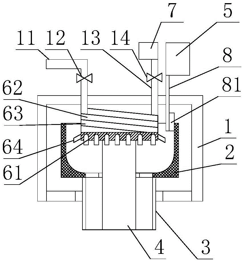
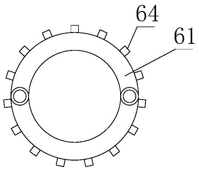
[0015] Such as figure 1 and 2 as shown, figure 1 It is a structural schematic diagram of a high-efficiency solid-liquid separation centrifuge proposed by the present invention, figure 2 for figure 1 A schematic top view of the annular jet in .

[0016] refer to figure 1 and 2 , a high-efficiency solid-liquid separation centrifuge proposed by the present invention, comprising: a casing 1, a drum 2, a discharge cylinder 3, a first drive device 4, a second drive device 5, a flow guide mechanism, an air injection mechanism 7, a scraper rod 8;

[0017] There is a cavity inside the casing 1, the bottom of the cavity has a first outlet for discharging solids and a second outlet for discharging liquid, the top of the casing 1 is provided with a liquid inlet and an air inlet, and the liquid inlet is provided with The liquid inlet pipe 11 is provided with a first valve 12, the air inlet is provided with an air inlet pipe 13, and the air inlet pipe 13 is provided with a second va...


PUM


Abstract

The invention discloses an efficient solid-liquid separating centrifugal machine. Materials to be separated are sprayed into a rotary cylinder along a spiral passage of a flow guiding mechanism, the direction of the materials entering the rotary cylinder is consistent with the rotating direction of the rotary cylinder, the flowing direction of fluid in the rotary cylinder cannot be disturbed when the materials to be separated enter the rotary cylinder, the centrifugal separating efficiency of the rotary cylinder is improved, liquid in the materials is thrown out through the rotary cylinder rotating at a high speed and is discharged out of a liquid discharge port after being accumulated through a machine shell, and solid phases in the materials are intercepted on the side wall of the rotary cylinder. When the speed of the centrifugal machine is reduced, a scraper rod vertically moves so that a scraper blade can extend into the rotary cylinder, liquid is stopped entering a liquid inlet pipe, gas sprayed by a gas spraying mechanism enters the rotary cylinder along the spiral passage of the flow guiding mechanism, gas is sprayed to the inner wall of the rotary cylinder, the scraper blade is assisted in efficient scraping of the inner wall of the rotary cylinder, and the scraped solid-phase materials are discharged out of a discharge cylinder. The efficient solid-liquid separating centrifugal machine is reasonable in structural arrangement, the centrifugal separating efficiency is improved, and the solid materials can be scraped away conveniently.

Description

technical field [0001] The invention relates to the technical field of centrifuges, in particular to a high-efficiency solid-liquid separation centrifuge. Background technique [0002] The centrifuge is a machine that uses the inertial centrifugal force generated by the rotation of the drum to separate or concentrate suspensions, emulsions and other heterogeneous materials. The working principle is: when the suspension to be separated enters the drum of the centrifuge, it is The rotating drum produces strong centrifugal force to deposit the solid phase particles on the inner wall of the drum, and is trapped in the drum by the filter screen, and the liquid phase is filtered out through the filter screen. During the centrifugation process, the liquid to be separated enters directly through the liquid inlet. In the drum, it will disturb the flow direction of the liquid in the drum and affect the separation effect. At the same time, solids with high humidity after centrifugatio...

Claims


Application Information

Patent Timeline
Patent Type & Authority Applications(China)
IPC IPC(8): B04B1/00B04B11/08
Inventor 崔李黄艳
Owner 苏州相城埭辰科技产业发展有限公司
Why Eureka
Try Eureka