
Frictioning machine

A technology of glue rubbing machine and material receiving mechanism, which is applied in the direction of coating and liquid coating device on the surface, etc., which can solve the problems of unable to discharge glue, poor control of glue amount, unprepared glue dispensing, etc.

Active Publication Date: 2015-09-09
SUZHOU RS TECH
View PDF10 Cites 12 Cited by
  • Summary
  • Abstract
  • Description
  • Claims
  • Application Information

AI Technical Summary

Problems solved by technology

The air in the liquid will leak after the glue valve is closed, and there will be glue at the needle. If the glue solidifies quickly, the glue will not come out. At the same time, the glue is not prepared, and the amount of glue is not easy to control. After the glue dries, the surface is still sticky, and the film is stuck on it. Due to the residual glue at the needle point, the above problems will occur.

Method used

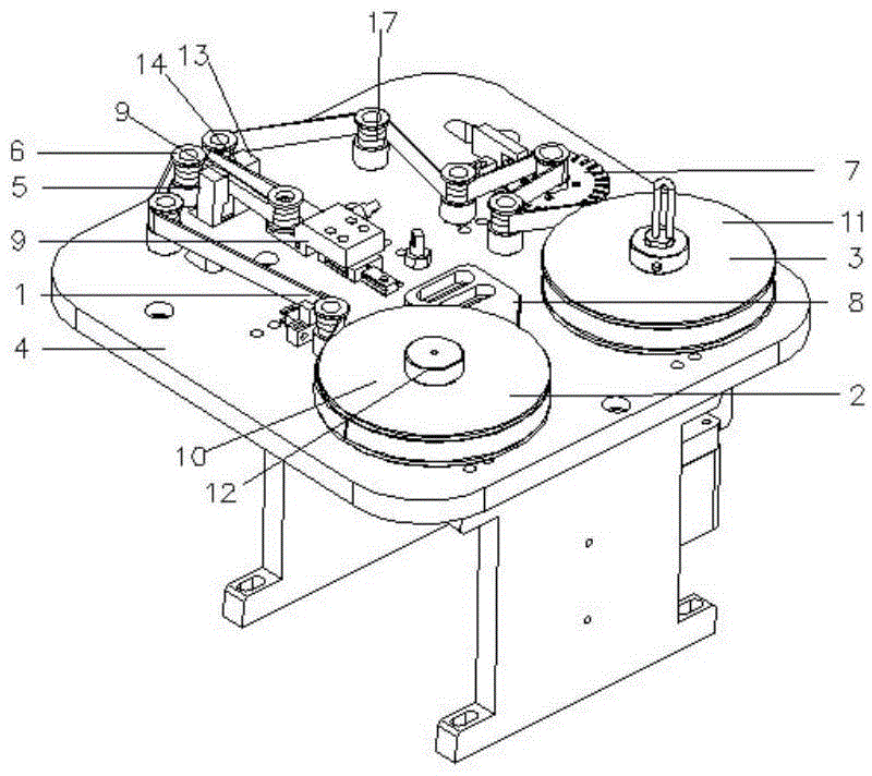
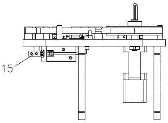
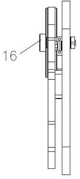

Image

  • Frictioning machine
  • Frictioning machine
  • Frictioning machine

Examples


Embodiment Construction

[0030] Such as figure 1 , 2 , A kind of glue wiping machine shown in 3, 4, comprises material belt 1, feeding mechanism 2, receiving mechanism 3, base 4, and described material belt 1 is fixed on the described feeding mechanism 2, passes through described feeding mechanism 2. Transport the material belt 1 so that the material belt 1 is in contact with the parts to be wiped. After the material belt 1 is wiped, it is recovered by the described material receiving mechanism 3, and the described material feeding mechanism 2 and the material receiving mechanism 3 are set On the base 4. After feeding mechanism 2, material belt 1, and material receiving mechanism 3, material belt 1 can be in close contact with the parts to be wiped. At this time, the glue of the parts in contact is wiped clean, and the parts to be wiped can be needles or glued. product. Material band 1 can wipe the relevant materials such as paper, cloth, rubber strip etc. and use.

[0031] The feeding mechanism 2...


PUM


Abstract

The invention discloses a frictioning machine, comprising a material strip, a feeding mechanism, a material recovering mechanism and a pedestal, wherein the material strip is fixed on the feeding mechanism and is conveyed by the feeding mechanism to allow the material strip to be contact with a to-be-frictionated part, the material strip is recovered by the material recovering mechanism after frictioning, and the feeding mechanism and the material recovering mechanism are arranged on the pedestal. Through the feeding mechanism, the material strip and the material recovering mechanism, the material strip closely contacts with the to-be-frictionated part and gum on the to-be-frictionated part is cleaned, so the problem of residual gum is overcome.

Description

technical field [0001] The invention relates to the glue dispensing industry, in particular to a glue wiping machine. Background technique [0002] At present, after each use of the dispensing machine, a needle that is too small will affect the flow of the liquid and cause back pressure, resulting in the phenomenon of dripping shortly after the glue valve is closed. A needle that is too small will also affect the air release action of the valve when it is first used. This problem can be solved by replacing the needle with a larger one. Tapered, angled needles create the least back pressure and allow the smoothest fluid flow. The air in the liquid will leak after the glue valve is closed, and there will be glue at the needle. If the glue solidifies quickly, the glue will not come out. At the same time, the glue is not prepared, and the amount of glue is not easy to control. After the glue dries, the surface is still sticky, and the film is stuck on it. Due to the residual g...

Claims


Application Information

Patent Timeline
IPC IPC(8): B05C11/00
Inventor 吴加富缪磊
Owner SUZHOU RS TECH
Learn More