Device and method for removing mud from rigid joints of underground diaphragm walls

An underground continuous wall and removal device technology, which is applied to cleaning methods and utensils, cleaning methods using tools, cleaning methods using liquids, etc. The effect of improving project cost and construction efficiency

Active Publication Date: 2017-03-01
CHINA RAILWAY 16 BUREAU GRP BEIJING METRO ENG CONSTR +2
View PDF7 Cites 0 Cited by
  • Summary
  • Abstract
  • Description
  • Claims
  • Application Information

AI Technical Summary

Problems solved by technology

"However, the lower end of the contact steel plate described in this patent is not in direct contact with the H-shaped steel, causing some attachments with strong adsorption force to be cut off directly, thus greatly increasing the difficulty of cleaning mud with wire brushes, and even causing wire brushes to The brushes are clogged, and the wire brushes need to be disassembled and cleaned repeatedly to continue to clear the mud, which reduces the construction efficiency
The device described in this patent is connected to the trough grab by high-strength bolts, and then the mud cleaning work is completed by controlling the lifting and lowering of the trough grab. The engineering cost is high, not economical and applicable, and the width of the trough grab is larger than the joint The length of the grooved grab bucket is arc-shaped, which does not match the shape of the joint, so the surrounding concrete and mud on the joint cannot be completely cleaned

Method used


Image

  • Device and method for removing mud from rigid joints of underground diaphragm walls
  • Device and method for removing mud from rigid joints of underground diaphragm walls
  • Device and method for removing mud from rigid joints of underground diaphragm walls

Examples


Embodiment 1

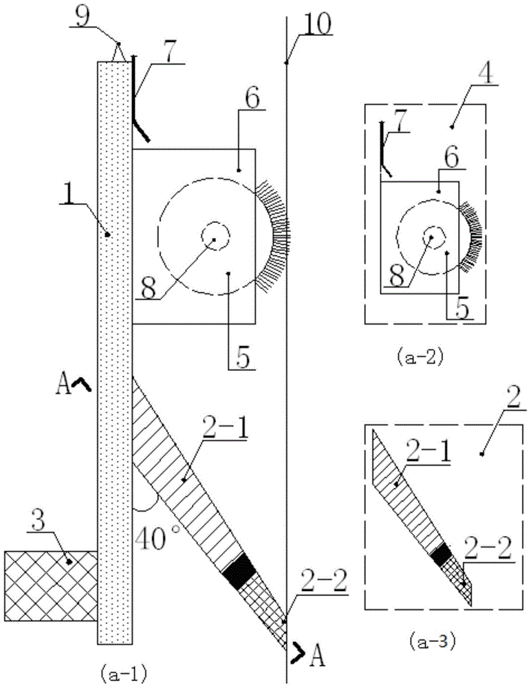
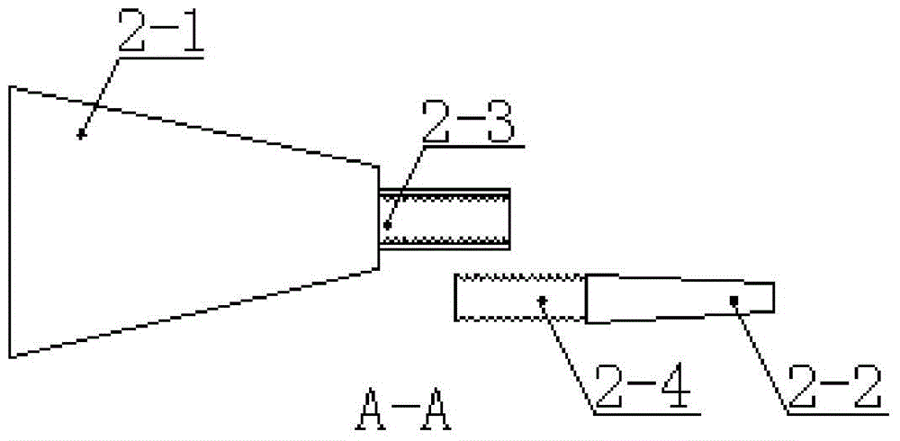
[0045] As shown in Figure 1(a) and Figure 1(b), this embodiment provides a mud removal device at the rigid joint of the underground diaphragm wall, the removal device includes: a fixed module 1, a mud removal module 2, a balance module 3, The water washing and rolling mud cleaning module 4, the suspension ring 9, and the connection relationship between each part are as follows:

[0046] The lifting rings 9 are evenly distributed on the top of the fixed module 1; the desilting module 2 is located on one side of the fixed module 1, and the position of the desilting module 2 is close to the bottom of the fixed module 1, and the desilting module 2 is fixedly connected with the fixed module 1; The mud module 4 and the mud removal module 2 are located on the same side, and the water washing and rolling mud cleaning module 4 is located close to the top of the fixed module 1. The water washing and rolling mud cleaning module 4 is connected to the fixed module 1 by welding through its o...

Embodiment 2

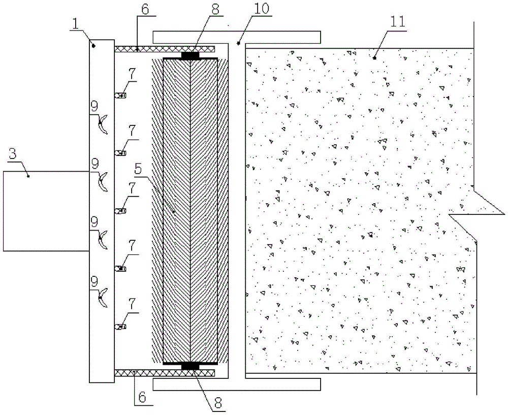
[0053] In this embodiment, a certain subway line is taken as an example. The design unit of the main enclosure structure adopts an underground diaphragm wall with a thickness of 1200mm and 5 vertical internal supports. The web height of 10 is 1000mm, and the depth of underground diaphragm wall 11 is 27m. The soil layer from top to bottom of the foundation groove side wall of underground diaphragm wall 11 can be divided into three types: the first type of soil layer is coarse sand layer and medium sand layer. layer, with a thickness of 3.0m and 4.2m; the second type of soil layer is clay, silty clay, and sandy clay layer, with a thickness of 3.0m, 4.2m, and 4.1m; the third type of soil layer is silty The clay and muddy soil are 4.4m and 4.1m thick respectively.

[0054] This embodiment provides a method for removing mud at the rigid joint of an underground diaphragm wall, the method is based on the removal device, and the specific implementation is as follows:

[0055] In the ...


PUM


Abstract

The invention provides an underground diaphragm wall rigid joint mud removal device and a method, which comprises the steps: 1 the underground diaphragm wall rigid joint mud removal device is positioned preliminarily on the other side of an I-shaped steel through a tower crane device after the strength of an underground diaphragm wall which is casted with concrete on one side of the I-shape steel which is arranged on an underground diaphragm wall rigid joint; 2 the lowering velocity of the underground diaphragm wall rigid joint mud removal device is determined according to practical geological conditions; 3 water injection pressure of a high pressure water injection pipe is determined according to the practical geological conditions; and 4 the high pressure water injection pipe in the underground diaphragm wall rigid joint mud removal device is opened, the water injection pressure of the high pressure water injection pipe is determined according to the step 3, and the underground diaphragm wall rigid joint mud removal device is lowered to the bottom portion of the underground continuous wall base slot in the lowering velocity which is determined in the step 2, thereby completing mud cleaning work of underground continuous wall rigid joints. The underground diaphragm wall rigid joint mud removal device and the method do not need to use a slotting machine to supply power, and reduce engineering cost simultaneously.

Description

technical field [0001] The invention relates to a construction method and a device in the technical field of underground construction engineering, in particular to a device and a method for removing mud at a rigid joint of an underground diaphragm wall. Background technique [0002] The form and quality of the joints between the various unit grooves of the underground diaphragm wall directly affect the working performance of the underground diaphragm wall. Common joint forms include rigid joints and flexible joints. At present, in the construction of underground diaphragm walls, the use of rigid joints is dominant. Since the underground diaphragm wall adopts the construction process of trough sections, it often results in a large amount of mud and flow-around concrete sticking to the side of the trough section formed in advance. It is necessary to use a special mud cleaning device to clean it. Generally, it needs to be cleaned more than 10 times before it can be cleaned. En...

Claims


Application Information

Patent Timeline
Patent Type & Authority Patents(China)
IPC IPC(8): B08B7/04B08B1/00B08B1/04B08B3/02
CPCB08B1/002B08B1/005B08B1/008B08B1/04B08B3/024B08B7/04E02D5/18E02D5/20
Inventor 朱小藻蔡连利高宪民周阳宗刘锐沈水龙范志高唐德刚余大成张益柱余贵良陶红杰黄帮兴闫江涛刘晓雪史运杰
Owner CHINA RAILWAY 16 BUREAU GRP BEIJING METRO ENG CONSTR
Why Eureka
Try Eureka