A heavy-duty automobile axle head forging parts manufacturing equipment

A technology for heavy-duty vehicles and manufacturing equipment, applied in the direction of manufacturing tools, metal processing equipment, maintenance and safety accessories, etc., can solve complex, inconvenient cutting or drilling, environmental pollution and other problems, and achieve easy operation, easy processing, and easy cutting or drilling effect

Active Publication Date: 2021-12-21
杨松梅
View PDF8 Cites 0 Cited by
  • Summary
  • Abstract
  • Description
  • Claims
  • Application Information

AI Technical Summary

Problems solved by technology

[0004] The purpose of the present invention is to solve the shortcomings of the existing shaft head forging parts, such as complex operation, inconvenient cutting or drilling, and inability to classify and collect the debris generated by processing, which is easy to cause environmental pollution, and proposes a Heavy-duty automobile axle head forging parts manufacturing equipment

Method used


Image

  • A heavy-duty automobile axle head forging parts manufacturing equipment
  • A heavy-duty automobile axle head forging parts manufacturing equipment
  • A heavy-duty automobile axle head forging parts manufacturing equipment

Examples


Embodiment 1

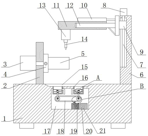
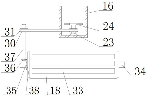
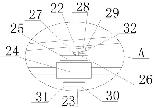
[0030] refer to Figure 1-6 , a kind of heavy-duty automobile axle head forging parts manufacturing equipment, comprising a body 1, a rotating structure is arranged on the top of the body 1, a workpiece 5 is connected to the rotating structure, a vertical plate 6 is fixedly connected to the top of the body 1, and a vertical plate 6 is arranged on the vertical plate 6 Lifting structure, the lifting structure is connected with a transverse bar 11, the bottom of the transverse bar 11 is connected with a cutting motor 13, the cutting motor 13 is connected with a cutting head 14, the top of the body 1 is provided with a dust guide groove 15 and a cavity 17, the cavity 17 and the dust guide groove 15 are connected with two dust suction tubes 16, and the dust-retaining structure is arranged in the two dust suction tubes 16, and the suction structure is installed in the rotation of the two dust suction tubes 16, and the cavity 17 A transmission structure is provided, and the transmiss...

Embodiment 2

[0041] refer to Figure 1-6 , a heavy-duty automobile shaft head forging parts manufacturing equipment, including a body 1, the top of the body 1 is provided with a rotating structure, a workpiece 5 is connected to the rotating structure, the top of the body 1 is fixedly connected with a vertical plate 6 by screws, and the vertical plate 6 is A lifting structure is provided, and a horizontal rod 11 is connected to the lifting structure, a cutting motor 13 is connected to the bottom of the horizontal rod 11, a cutting head 14 is connected to the cutting motor 13, and a dust guide groove 15 and a cavity 17 are arranged on the top of the body 1. Two dust suction tubes 16 are connected between the cavity 17 and the dust guide groove 15. The two dust suction tubes 16 are all provided with a dust-proof structure, and the two dust suction tubes 16 are all rotatably installed with an air suction structure. 17 is provided with a transmission structure, the transmission structure is ada...


PUM


Abstract

The invention belongs to the technical field of automobile axle head processing, in particular to a manufacturing equipment for heavy-duty automobile axle head forging parts. The manufacturing process of the existing axle head forging parts is complicated to operate, it is not convenient for cutting or drilling, and it cannot repair the broken parts produced by processing. Classification and collection of swarf can easily cause environmental pollution. The following scheme is proposed, which includes the body. The top of the body is provided with a rotating structure, and the workpiece is connected to the rotating structure. The top of the body is fixedly connected with a vertical plate. There is a lifting structure, the lifting structure is connected with a horizontal rod, the bottom of the horizontal rod is connected with a cutting motor, and the cutting motor is connected with a cutting head. Two dust suction cylinders are connected, and the invention is convenient to operate, to process workpieces, to cut or drill holes, and to classify and collect debris generated during processing, thereby reducing environmental pollution.

Description

technical field [0001] The invention relates to the technical field of automobile axle head processing, in particular to a manufacturing equipment for heavy-duty automobile axle head forging parts. Background technique [0002] The shaft head refers to the two ends of the shaft. The shaft is a mechanical part that supports the rotating parts and rotates with it to transmit motion, torque or bending moment. It is generally in the shape of a metal round rod, and each section can have different diameters. The rotary motion in the machine The parts of the shaft are installed on the shaft, and the two ends of the shaft are usually called the shaft head. The function of the shaft head part is usually to install the bearing and the hub, and the installation of the hub needs to be drilled on the shaft head. [0003] The manufacturing process of the existing shaft head forging parts is complicated to operate, it is not convenient for cutting or drilling, and it is impossible to class...

Claims


Application Information

Patent Timeline
Patent Type & Authority Patents(China)
IPC IPC(8): B23Q5/02B23Q5/26B23Q11/00B23Q11/10B03C1/02
CPCB23Q5/26B23Q5/02B23Q11/00B23Q11/10B03C1/02B23Q11/005B23Q11/1069
Inventor 杨明清
Owner 杨松梅
Why Eureka
Try Eureka