
Method and die for obtaining variable-intensity hot stamping part

A variable-strength, hot-stamping technology, applied in the field of hot-stamping, can solve problems such as inability to form variable-strength hot-stamped parts, and achieve the effect of improving comprehensive mechanical properties, easy implementation, and broad application prospects

Active Publication Date: 2015-09-09
WUHAN UNIV OF TECH
View PDF6 Cites 24 Cited by
  • Summary
  • Abstract
  • Description
  • Claims
  • Application Information

AI Technical Summary

Problems solved by technology

[0005] The purpose of the present invention is to provide a method and mold for obtaining variable-strength hot stamping parts, which can make different regions of hot stamping parts have different structures and strengths, realize the multi-performance requirements of a single part, and effectively solve the traditional hot stamping forming process Technical Difficulties in Unable to Form Stamped Stamping Parts with Stress Strength

Method used


Image

  • Method and die for obtaining variable-intensity hot stamping part
  • Method and die for obtaining variable-intensity hot stamping part
  • Method and die for obtaining variable-intensity hot stamping part

Examples


Embodiment Construction

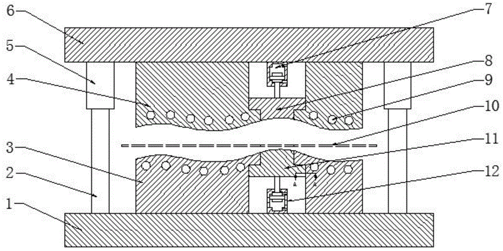
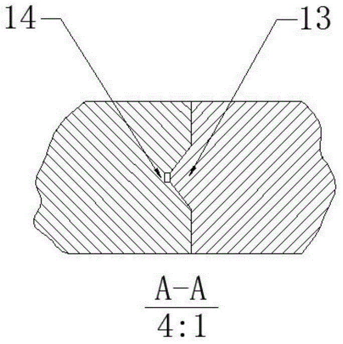
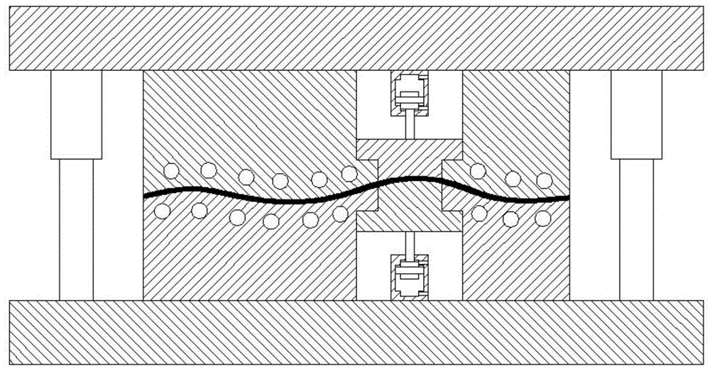
[0037] Let's take the B-pillar parts with variable strength as an example in combination with the attached Figure 1a , 1b ~4, further illustrate the content of the present invention and its specific implementation steps.

[0038] A method for obtaining variable-strength hot stamping parts, comprising the steps of:

[0039] Step 1: Mold preparation.

[0040] A mold for obtaining variable-strength hot stamping parts, including an upper mold mounting plate 6, a lower mold mounting plate 1, a guide post 2, a guide sleeve 5, an upper mold fixed insert 4, an upper mold movable insert 8, a lower mold fixed insert Block 3, lower mold movable insert 11, upper hydraulic cylinder 7, lower hydraulic cylinder 12; upper mold fixed insert 4 is fixed on upper mold mounting plate 6, upper mold fixed insert 4 is provided with cooling channel 9 (cooling 9 communicates with the cooling pipe to provide cooling), the fixed insert 4 of the upper die is also provided with a through hole for instal...


PUM


Abstract

The invention relates to the field of hot stamping forming and discloses a method and a die for obtaining a variable-intensity hot stamping part. The method for obtaining the variable-intensity hot stamping part is characterized by including steps that 1) preparing the die; 2) preparing; 3) stamping, to be specific, quickly moving a completely austenitized part blank to the die from a heating furnace; enabling a fixed insert of an upper die and a movable insert of the upper die to synchronously move downward till the die is closed, and finishing the hot stamping forming; 4) maintaining pressure and quenching, to be specific, quenching the constant-intensity region of the part by means of a die cooling system, and enabling the austenite to completely convert into a martensitic structure; enabling the movable insert of the upper die and a movable insert of a lower die corresponding to the variable-intensity region of the part to separate from the surface of the variable-intensity region of the part after maintaining a closed pressure maintaining state for 1 to 3 seconds, and forming a clearance; 5) returning and taking the part, to be specific, enabling the fixed insert of the upper die and the movable insert of the upper die to synchronously move towards the upside, opening the die, and taking out the part. The method for obtaining the variable-intensity hot stamping part can make different regions of the hot stamping part have different structures and intensities, and the multi-performance requirement of a single part is realized.

Description

technical field [0001] The invention relates to the field of hot stamping forming, and more specifically, relates to a manufacturing method and mold of a variable-strength hot stamping part. Background technique [0002] As the energy crisis and environmental issues become increasingly prominent and people pay more and more attention to automobile safety, safety, energy saving and environmental protection have become the development trend of today's automobile industry. Hot stamping forming technology can effectively solve the problems of poor stamping performance and large springback of high-strength steel plates, and is an effective way to achieve energy saving, emission reduction and vehicle weight reduction. [0003] The hot stamping forming technology is to heat the steel plate to the austenitic state, pressurize and quench after rapid stamping to obtain ultra-high-strength steel parts with martensitic structure. After hot stamping, the strength of the obtained parts c...

Claims


Application Information

Patent Timeline
IPC IPC(8): B21D22/02B21D37/10C21D1/18C21D9/00
Inventor 宋燕利华林任永强路珏韩瑜沈玉含
Owner WUHAN UNIV OF TECH
Learn More