O-shaped ring taking and releasing mechanism

A technology for picking and placing materials and O-rings, applied in metal processing, metal processing equipment, manufacturing tools, etc., can solve problems such as poor operation stability, low degree of automation, and difficult O-rings, and achieve high work efficiency and automation High degree and good operation stability

Inactive Publication Date: 2015-09-09
ZHUJI RUN TUO MECHANICAL AUTOMATION TECH
View PDF7 Cites 11 Cited by
  • Summary
  • Abstract
  • Description
  • Claims
  • Application Information

AI Technical Summary

Problems solved by technology

[0004] The above-mentioned scheme solves the problems of difficulty and low efficiency of the existing manual assembly of O-rings to a certain extent, but the scheme still has problems such as low degree of automation, poor operation stability, and poor assembly effect.

Method used


Image

  • O-shaped ring taking and releasing mechanism
  • O-shaped ring taking and releasing mechanism
  • O-shaped ring taking and releasing mechanism

Examples


Embodiment Construction

[0021] The present invention will be described in further detail below in conjunction with the accompanying drawings and specific embodiments.

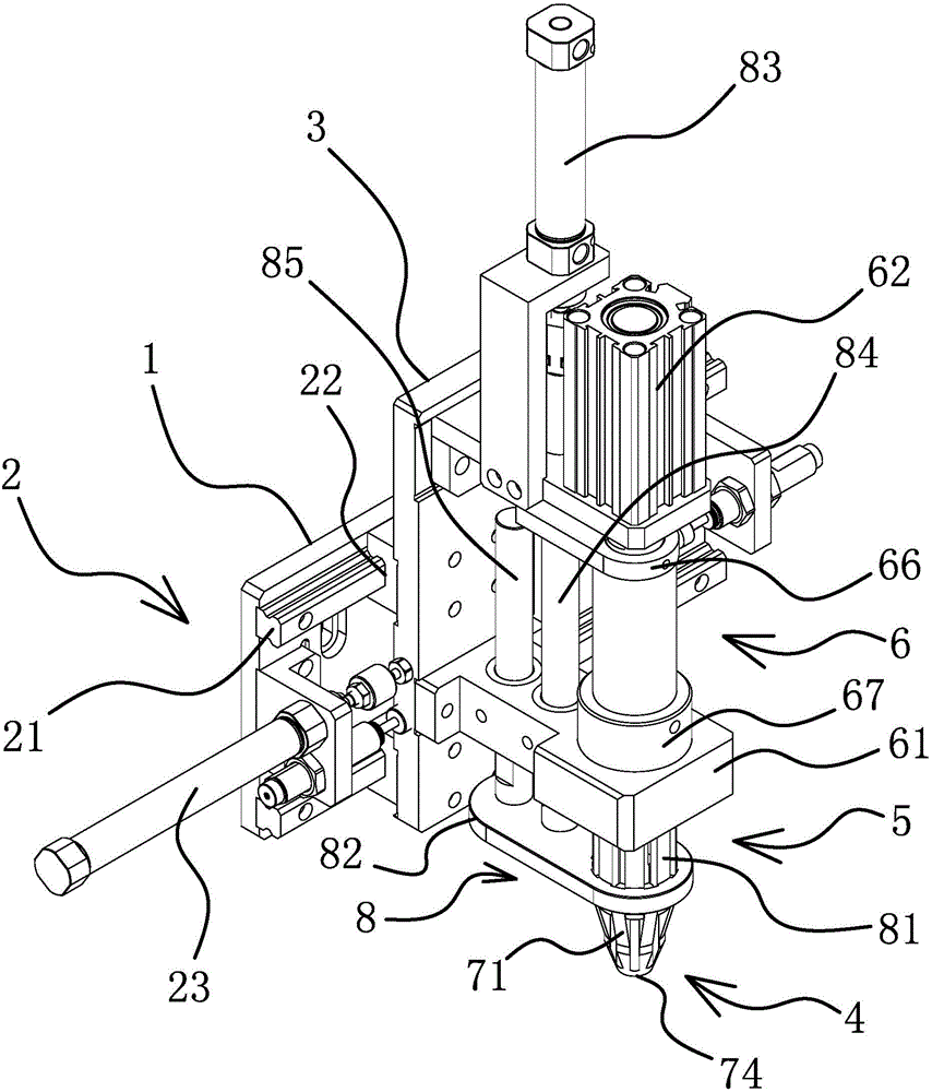
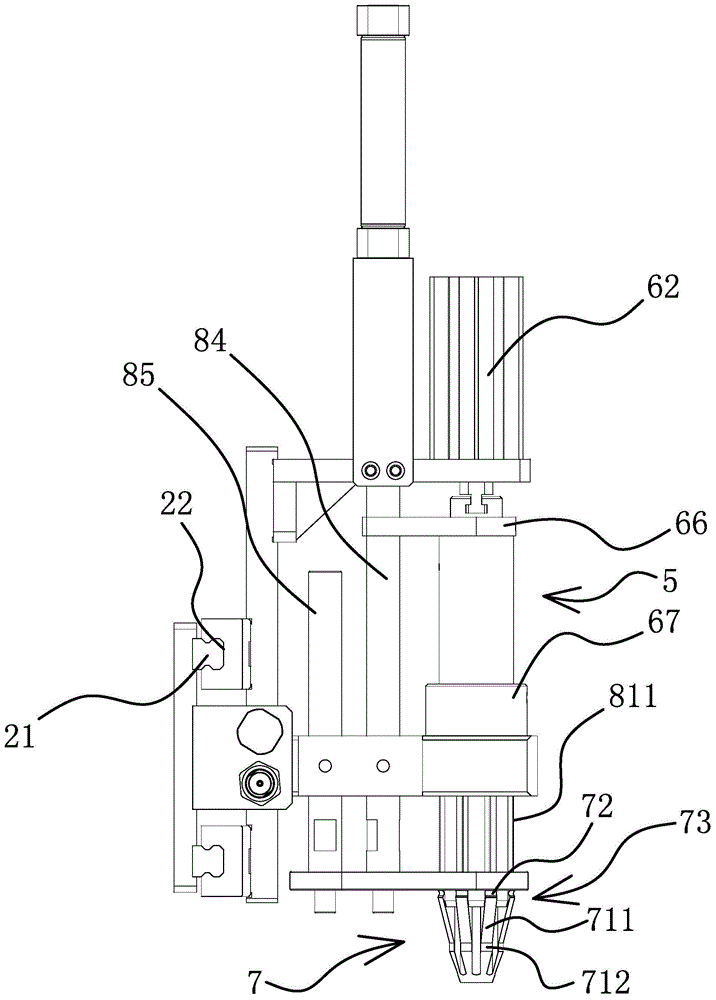
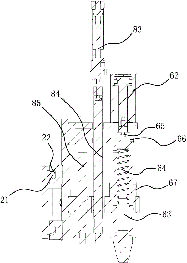
[0022] Such as Figure 1-3 As shown, the O-ring take-and-discharge mechanism includes a frame body 1, and a horizontal frame 3 that can move laterally along the frame body 1 is provided on the frame body 1 through a lateral drive structure 2. For example, the lateral drive structure 2 here can be It includes a slide bar 21 horizontally arranged on the frame body 1, a chute 22 matching the slide bar 21 is provided on the inner side of the transverse frame 3, and a drive slide bar 21 and a slide bar are provided between the frame body 1 and the transverse frame 3. The transverse drive 23 that the groove 22 slides mutually, the transverse drive 23 here can adopt the motor that links to each other with frame body 1 to drive screw mandrel to rotate, be provided with the screw sleeve that links to each other with transverse frame 3 on screw...


PUM


Abstract

The invention relates to an O-shaped ring taking and releasing mechanism and solves the problems of low assembly efficiency of prior O-shaped rings and the like. The mechanism comprises a frame, a transverse frame capable of moving along the frame transverse direction is arranged on the frame, and a tapered taking claw and an assembly cone are arranged on the transverse frame in a sliding mode and are both connected with a taking and releasing drive structure. A location structure capable of locating the O-shaped ring on the tapered taking claw when the tapered taking claw moves downwards axially is arranged on the tapered taking claw, and an assembly location structure capable of separating the O-shaped ring from the tapered taking claw and locating the tapered taking claw on a work-piece when the assembly cone moves downwards axially is arranged on the assembly cone. The mechanism has the advantages of being simple in structure, high in automatic degree and work efficiency, good in operation stability, capable of achieving taking and releasing of the O-shaped ring and assembling the O-shaped ring on the work-piece and good in assembly effect.

Description

technical field [0001] The invention belongs to the technical field of automation equipment, and in particular relates to an O-ring feeding and discharging mechanism. Background technique [0002] The O-ring is a rubber sealing ring with a circular cross-section. Because of its O-shaped cross-section, it is called an O-shaped rubber sealing ring, also called an O-ring. It can be used in static applications as well as dynamic applications where there is relative motion between parts. At present, the common O-ring is assembled on the workpiece mainly by manual means, that is, the O-ring is set on the workpiece manually. This method has low labor intensity, high labor cost, poor assembly effect and low efficiency. These problems greatly restrict the assembly of the existing O-ring. [0003] In order to solve the problems existing in the prior art, people have carried out long-term exploration and proposed various solutions. For example, Chinese patent literature discloses an...

Claims


Application Information

Patent Timeline
Patent Type & Authority Applications(China)
IPC IPC(8): B23P19/04
CPCB23P19/001B23P19/04
Inventor 俞才王
Owner ZHUJI RUN TUO MECHANICAL AUTOMATION TECH
Why Eureka
Try Eureka