
Pit-type tempering furnace with pressure control function

A pressure control and tempering furnace technology, which is applied in heat treatment process control, manufacturing tools, heat treatment equipment, etc., can solve the problems of uneven heating in different areas, temperature rise, dead ends, etc., to eliminate dead ends of hot air circulation, ensure the quality of finished products, and facilitate the take out effect

Inactive Publication Date: 2015-09-09
李华良
View PDF5 Cites 9 Cited by
  • Summary
  • Abstract
  • Description
  • Claims
  • Application Information

AI Technical Summary

Problems solved by technology

[0002] The tempering furnace is used for tempering general metal parts in the air and quenching, annealing and aging heat treatment for aluminum alloy die castings, pistons, aluminum plates and other light alloy parts; the metal castings required for valve manufacturing must be tempered. Improve its mechanical properties; the tempering furnace in the prior art has parts in different areas of the furnace that are heated evenly, and the processing results of the parts are quite different when processing a large number of parts. Although the effect is improved by adding a hot air circulation system, when After a large number of parts are loaded into the furnace, the hot air circulation is hindered by the parts, resulting in dead angles in the furnace. At the same time, the placement of the parts cannot be completely consistent, resulting in uneven heating in different areas, and there are obvious differences in the process of temperature rise, maintenance and drop, which eventually leads to The processing results between the parts are inconsistent; and the tempering furnace is in a sealed state, and the high temperature for a long time will easily cause excessive pressure in the furnace body, making it difficult to open the furnace body, and the temperature continues to rise under high pressure, which affects the tempering effect

Method used


Image

  • Pit-type tempering furnace with pressure control function

Examples


Embodiment Construction

[0010] The following will clearly and completely describe the technical solutions in the embodiments of the present invention with reference to the accompanying drawings in the embodiments of the present invention. Obviously, the described embodiments are only some, not all, embodiments of the present invention. Based on the embodiments of the present invention, all other embodiments obtained by persons of ordinary skill in the art without making creative efforts belong to the protection scope of the present invention.

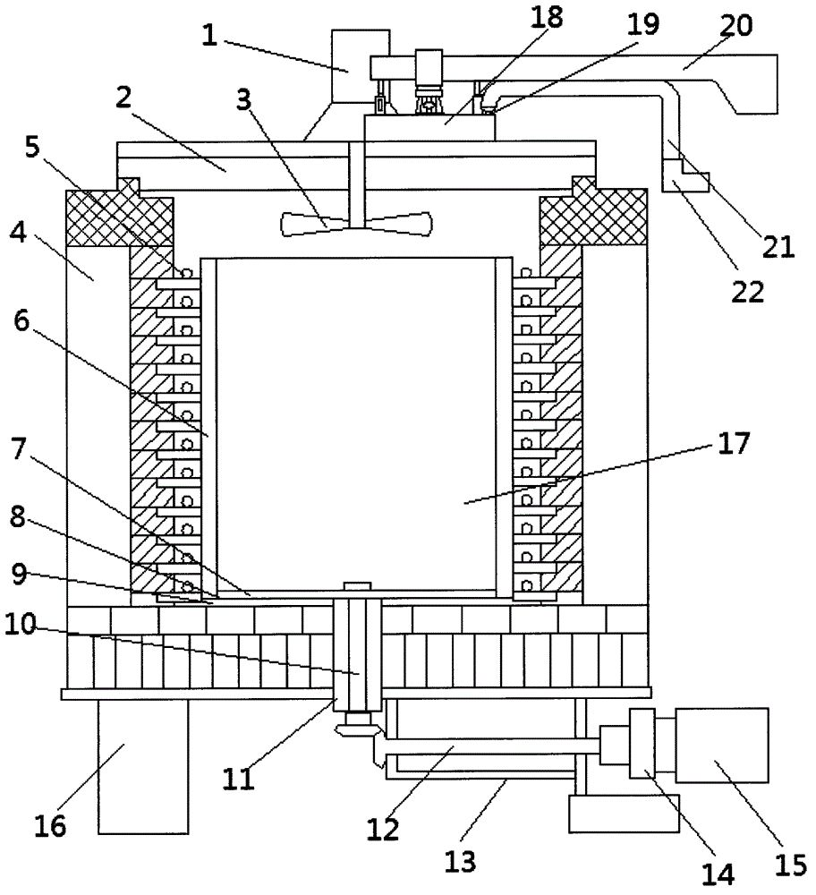
[0011] see figure 1 , in an embodiment of the present invention, a pressure-controlled well-type tempering furnace includes a furnace cover 2 and a shell 4, the furnace cover 2 is installed on the upper part of the shell 4, and a heating pipe 5 and a guide air are arranged in the shell 4 There are multiple heating tubes 5 wrapped around the outside of the air guide tube 6, the interior of the air guide tube 6 is a tempering chamber 17, and the hot air forced c...


PUM


Abstract

The invention discloses a pit-type tempering furnace with a pressure control function. The pit-type tempering furnace comprises a furnace cover and a casing, wherein the furnace cover is mounted at the upper part of the casing; heating pipes and an air duct are arranged in the casing; the air duct is covered with the multiple heating pipes; a rotating platform is arranged in a furnace body and can rotate continuously and stably; the rotating platform drives a metal casting to rotate in different directions at different speeds in a heating process, heated air circulation dead angles in the furnace body are eliminated, different areas in a tempering chamber are heated uniformly, further, the metal casting is heated uniformly, and consistent quality of finished products can be guaranteed when massive metal castings are subjected to tempering processing; a smoke exhausting system arranged on the furnace cover solves the problem that the processing effect is affected by continuous increased temperature due to overhigh pressure in the furnace body, can open an auxiliary cover in advance to reduce the pressure in the furnace body and exhausts high-temperature gas in the furnace body when the metal casting is taken out after tempering, and the metal casting is taken out conveniently.

Description

technical field [0001] The invention relates to the field of valve production equipment, in particular to a pressure-controlled well-type tempering furnace. Background technique [0002] The tempering furnace is used for tempering general metal parts in the air and quenching, annealing and aging heat treatment for aluminum alloy die castings, pistons, aluminum plates and other light alloy parts; the metal castings required for valve manufacturing must be tempered. Improve its mechanical properties; the tempering furnace in the prior art has parts in different areas of the furnace that are heated evenly, and the processing results of the parts are quite different when processing a large number of parts. Although the effect is improved by adding a hot air circulation system, when After a large number of parts are loaded into the furnace, the hot air circulation is hindered by the parts, resulting in dead angles in the furnace. At the same time, the placement of the parts canno...

Claims


Application Information

Patent Timeline
IPC IPC(8): C21D1/18C21D11/00
Inventor 李华良
Owner 李华良
Learn More