Automatic water level adjusting drainage anti-slide pile and construction method thereof
An automatic adjustment and anti-slide pile technology, which is applied in excavation, sheet pile walls, foundation structure engineering, etc., can solve the problems of high cost, difficult operation, and inability to automatically adjust the water level, so as to reduce potential danger and reduce dynamic water pressure , good drainage effect
- Summary
- Abstract
- Description
- Claims
- Application Information
AI Technical Summary
Problems solved by technology
Method used
Image
Examples
Embodiment 1
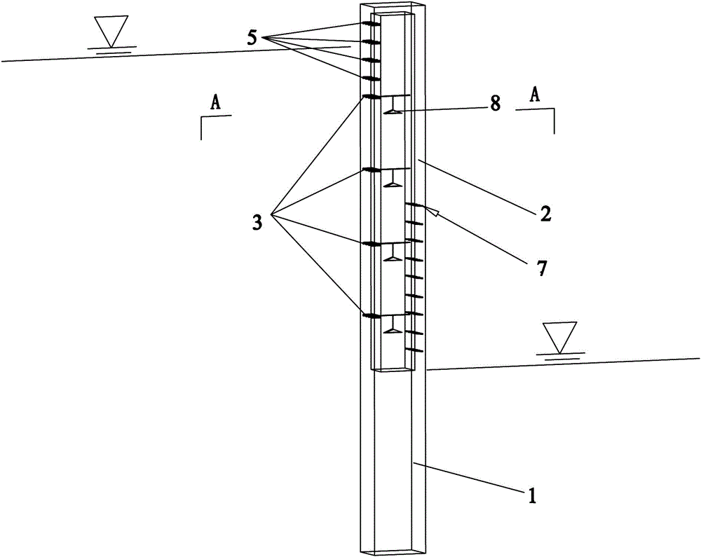
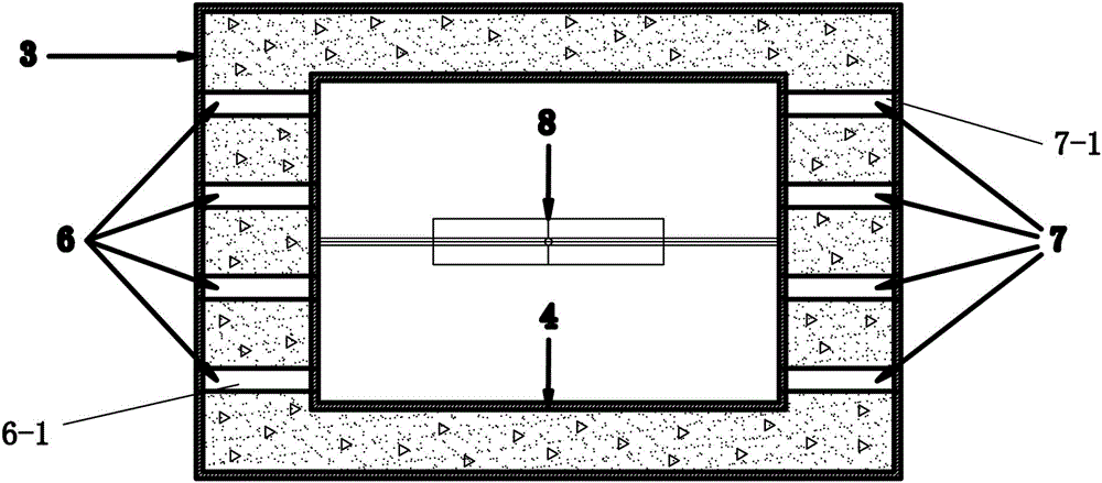
[0049] Such as Figure 1-Figure 8 As shown, a drainage anti-slide pile that automatically adjusts the water level includes a pile body 1 formed by pouring concrete on a steel cage,
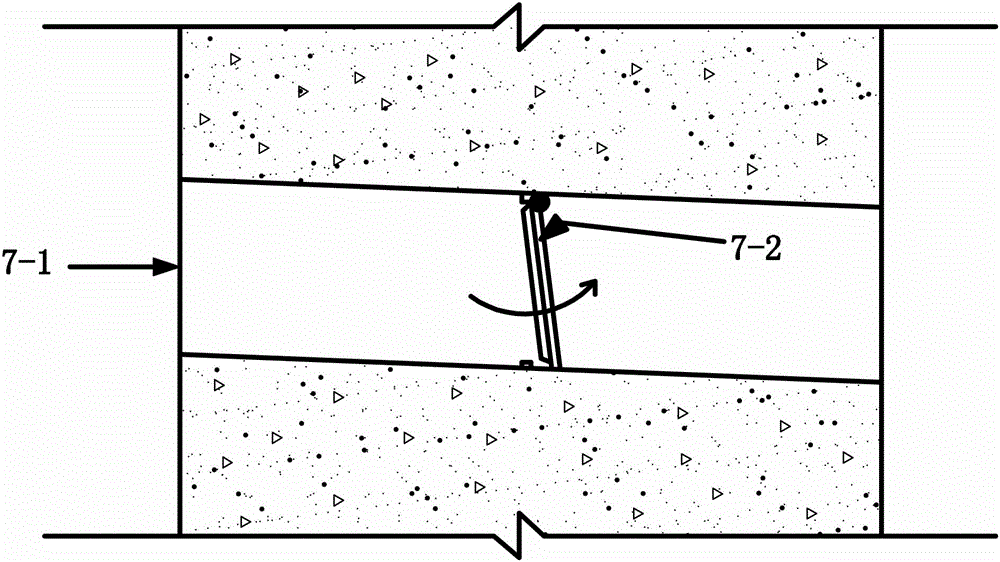
[0050] The pile body consists of a concrete pile body 1 and a rectangular hollow pile body 2 arranged on the concrete pile body 1. An outer steel formwork 3 is surrounded on the outside of the pile body, and an inner steel formwork 4 is surrounded on the rectangular hollow pile body 2. The rectangular hollow pile body The upper part of one side of the tensile end of 2 is provided with multiple groups of water inlet pipe groups 5 in parallel in the longitudinal direction, and the lower part of the side of the tensile end of the rectangular hollow pile body 2 is provided with multiple groups of adjustable water inlet pipe groups 6 in parallel with the longitudinal direction, and the rectangular hollow pile body 2 There are multiple groups of outlet pipe groups 7 arranged parallel to the longitudinal...
Embodiment 2
[0064] A construction method of a drainage anti-slide pile that automatically adjusts the water level, the method includes the following steps:
[0065] 1) Design the water inlet pipe group 5, adjust the water inlet pipe group 6 and the water outlet pipe group 7: according to the distribution of groundwater and the size of the pile body, reasonably design the water inlet pipe group 5, adjust the size of the water inlet pipe group 6 and the water outlet pipe group 7, quantity and location;
[0066] 2) Make the reinforcement cage, the outer steel formwork 3 and the inner steel formwork 4 to form an overall skeleton: under the premise of considering the water inlet pipe group 5, adjusting the size, quantity and position of the water inlet pipe group 6 and the water outlet pipe group 7, according to the pile body Force configuration reinforcement cage, outer steel formwork 3 and inner steel formwork 4;
[0067] 3) Install the hole opening device 8: in the cavity formed by the inn...
Embodiment 3
[0075] Such as Figure 11 Shown, adopt the drainage anti-slide pile of the present invention to carry out the process of drainage as follows:
[0076] After the construction of the anti-slide pile is completed, a wetting line 10 will be formed in the slope body 9 due to the change of the water level;
[0077] When the water level of the reservoir rises, the groundwater level also rises at the same time, and the inlet pipe hole covers 6-3 of each adjusting water inlet pipe group are closed due to the constraints of the first crossbar 8-3 and the second crossbar 8-4. After a certain height, water will flow into the cavity of the pile body from each water inlet pipe group 5 on the top of the rectangular hollow section pile body 2, so that the water level in the pile body will continue to rise, and the floating body 8-1 of the opening device 8 will be subject to buoyancy The action moves upwards (eg Figure 10 shown), and then drive one end of the first crossbar 8-3 to perk, and...
PUM
 Abstract
Description
Claims
Application Information
 - R&D
- Intellectual Property
- Life Sciences
- Materials
- Tech Scout
- Unparalleled Data Quality
- Higher Quality Content
- 60% Fewer Hallucinations
Browse by: Latest US Patents, China's latest patents, Technical Efficacy Thesaurus, Application Domain, Technology Topic, Popular Technical Reports.
© 2025 PatSnap. All rights reserved.Legal|Privacy policy|Modern Slavery Act Transparency Statement|Sitemap|About US| Contact US: help@patsnap.com


