Centripetal type compressor

A compressor, axial technology, applied in the field of impeller machinery, can solve the problems of increasing system instability, increasing manufacturing costs, large axial force, etc., and achieving the effects of improving work efficiency, avoiding vibration, and reducing gap loss.

Inactive Publication Date: 2015-09-09
UNIV OF SHANGHAI FOR SCI & TECH
View PDF7 Cites 4 Cited by
  • Summary
  • Abstract
  • Description
  • Claims
  • Application Information

AI Technical Summary

Problems solved by technology

[0007] Common centrifugal compressors cause a large axial force due to their single-ended air intake, which requires a large bearing force to balance and increase manufacturing costs; there is a gap between the top and wall of the existing centrifugal compressor blades, so it will gap loss
In the existing centrifugal compressor motor, only one end of the vane is fixed, and the other end is exposed, so large vibrations will be generated during the rotation process, increasing the instability of the system

Method used


Image

  • Centripetal type compressor
  • Centripetal type compressor
  • Centripetal type compressor

Examples


Embodiment Construction

[0022] The centripetal compressor involved in the present invention will be described in detail below in conjunction with the accompanying drawings.

[0023]

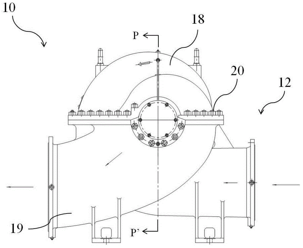
[0024] figure 1 It is the structural representation of the centripetal compressor of embodiment;

[0025] figure 2 yes figure 1 The cross-sectional view of the P-P' direction.

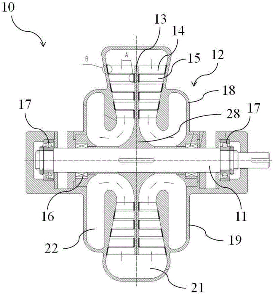
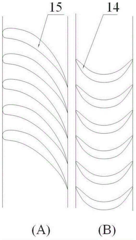
[0026] Such as figure 1 , 2 As shown, the centripetal compressor 10 includes a rotating shaft 11 , a casing 12 , a disc 13 , multiple sets of moving blade cascades 14 , multiple sets of stationary blade cascades 15 and a sealing body 16 .

[0027] The rotating shaft 11 is rotatably fixed on the bearings 17 at both ends, and drives the wheel disc 13 to rotate. The rotating shaft 11 is externally connected to a motor or other prime movers (not shown in the figure).

[0028] The casing 12 is used to protect the centripetal compressor 10 . In this embodiment, the casing 12 includes an upper casing 18 and a lower casing 19 , and the upper c...


PUM


Abstract

The invention provides a centripetal type compressor. The centripetal type compressor is characterized in that the compressor comprises an axially symmetrical rotary shaft, a housing body, axially symmetrical wheel discs, multiple groups of axially symmetrical movable blade lattices, multiple groups of axially symmetrical static blade lattices, and a sealing body. The rotary shaft is used for fixing and driving the wheel discs to rotate. The housing body comprises an air charging volute and an air discharging volute, which are axially symmetrically arranged. The wheel discs are capable of rotating around a central shaft. One end of each movable blade lattice is fixed on one wheel disc, and the other end is rotatably embedded into the housing body via a movable blade shroud ring and id driven to rotate by the wheel disc so as to drive air flows to move. One end of the static blade lattice is fixed on the housing body and the other end rotatably embedded into the housing body via a static blade shroud ring. The sealing body used for preventing air leakage is arranged at a joint of the rotary shaft and the housing body. The movable blade lattices and the static blade lattices are alternatively arranged in the radial direction of the rotary shaft and one group of the static blade lattices is closest to the rotary shaft. Each of the movable blade lattices and each of the static blade lattices are straight blades. The shape of cross section of each of the straight blades is invariable in the height direction of the blade.

Description

technical field [0001] The invention relates to the field of impeller machinery, in particular to a multi-stage centripetal air compressor with two-way air outlet. Background technique [0002] The impeller compressor is mainly divided into axial flow type and radial flow type. [0003] The shape and flow characteristics of the axial flow compressor are suitable for use in the multi-stage compression process. Its structure is complex, the axial dimension is long, and the stable working range is small. Compared with the axial flow compressor, the radial flow compressor has a simpler structure, smaller weight and volume, and can maintain high efficiency in a wide operating range. It is widely used in the fields of vehicles, ships, some industrial compressors and aviation compressors. There are a wide range of applications. [0004] Due to the different linear speeds of rotation at different radial positions in existing axial flow compressors, twisted blades must be used. Eve...

Claims


Application Information

Patent Timeline
Patent Type & Authority Applications(China)
IPC IPC(8): F04D17/02F04D29/44F04D29/66F04D29/26F04D29/08
Inventor 黄典贵李银各谭鑫
Owner UNIV OF SHANGHAI FOR SCI & TECH
Why Eureka
Try Eureka