Novel Co<2> multi-stage throttle frost valve

A throttling antifreeze valve, CO2 technology, applied in the field of throttling valves, can solve the problems of valve body and pipeline behind the valve freezing, low fluid temperature, etc., achieve the effects of alleviating impact wear, reducing labor intensity, and improving equipment maintenance efficiency

Inactive Publication Date: 2015-09-09
CHINA UNIV OF PETROLEUM (EAST CHINA)
View PDF5 Cites 2 Cited by
  • Summary
  • Abstract
  • Description
  • Claims
  • Application Information

AI Technical Summary

Problems solved by technology

However, the large pressure difference throttling of high-pressure fluid often produces a large temperature drop, which will cause the fluid temperature behind the valve to be low, and then cause the risk of freezing of the valve body and the pipeline behind the valve

Method used


Image

  • Novel Co&lt;2&gt; multi-stage throttle frost valve
  • Novel Co&lt;2&gt; multi-stage throttle frost valve

Examples


Embodiment Construction

[0024] The present invention will be further described below in conjunction with accompanying drawing:

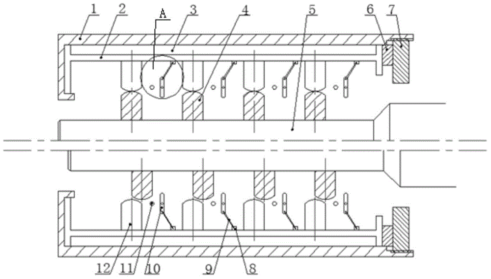
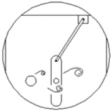
[0025] Depend on figure 1 and figure 2 As shown, a new type of CO 2 The multi-stage throttling antifreeze valve includes a valve body 1, a valve cylinder 2, a valve core 5 and a friction heating system, wherein the valve cylinder 2 is set inside the valve body 1, the valve core 5 is set inside the valve cylinder 2, and the valve cylinder 2. Several stages of valve cylinder components 12 are provided on the inner wall, and several stages of valve core components 4 are provided on the outer wall of the valve core 5 to cooperate with the several stages of valve cylinder components 12 respectively. The valve core components 4 and the valve cylinder components 12 cooperate To form or close the throttling channel, the friction heating system includes an annulus 3 for containing heat transfer medium and several sets of friction devices, the annulus 3 is arranged between the val...


PUM


Abstract

The invention relates to a novel Co<2> throttle frost valve comprising a valve body, a valve cylinder, a valve core and a friction heating system. The valve cylinder is disposed in the valve body; the valve core is disposed in the valve cylinder; a plurality stages of valve cylinder components are arranged on the inner wall of the valve cylinder; the outer wall of the valve core is provided with a plurality stages of valve core components one-to-one corresponding to the plurality stages of valve cylinder components; the friction heating system is formed by a hohlraum accommodating heat conducting medium and a plurality sets of friction devices; the hohlraum is placed between the valve body and the valve cylinder; the plurality of friction devices are behind each cooperation part between each stage valve cylinder component and each stage valve core component; and the friction devices are connected with the valve cylinder. With the friction heating system, fluid after throttling can be heated, so temperature of the fluid after the throttling can be maintained and damage to the valve body and pipelines behind the valve can be prevented; cavitation can be reduced and eliminated; impact wear of valve internal components by Co<2> can be reduced; and service life of a throttle valve can be prolonged.

Description

technical field [0001] The invention belongs to the technical field of throttle valves, in particular to a novel CO 2 Multi-stage throttling antifreeze valve. Background technique [0002] With the increasing severity of the greenhouse effect, the reduction of greenhouse gas emissions has also received increasing attention internationally. CCUS (Carbon Capture, Transport, Storage and Utilization) technology emerges at the historic moment, and CO2 needs to be transported by pipelines at the capture site and storage site. 2 . And relevant studies have shown that high pressure (supercritical state) transport of carbon dioxide is a feasible solution. In order to control the pressure and flow of the fluid on the pipeline, a throttle valve needs to be set. However, the large pressure difference throttling of high-pressure fluid often produces a large temperature drop, which will lead to a low temperature of the fluid behind the valve, thereby causing the risk of freezing of th...

Claims


Application Information

Patent Timeline
Patent Type & Authority Applications(China)
IPC IPC(8): F16K1/36F16K1/32F16K49/00
CPCF16K1/32F16K1/36F16K49/00
Inventor 滕霖李玉星张大同
Owner CHINA UNIV OF PETROLEUM (EAST CHINA)
Why Eureka
Try Eureka