Tank connecting structure of no-header plate heat exchanger

A heat exchanger and box plate technology, applied in the field of connection structure, can solve the problems of occupying space and difficult to achieve miniaturization, and achieve the effects of material saving, improving pressure resistance and ensuring strength

Inactive Publication Date: 2015-09-09
T RAD CO LTD
View PDF6 Cites 10 Cited by
  • Summary
  • Abstract
  • Description
  • Claims
  • Application Information

AI Technical Summary

Problems solved by technology

[0016] In addition, in the tank connection structure by riveting as described above, the small flange portion of the tank protrude...

Method used


Image

  • Tank connecting structure of no-header plate heat exchanger
  • Tank connecting structure of no-header plate heat exchanger
  • Tank connecting structure of no-header plate heat exchanger

Examples


Embodiment Construction

[0080] Next, embodiments of the present invention will be described based on the drawings.

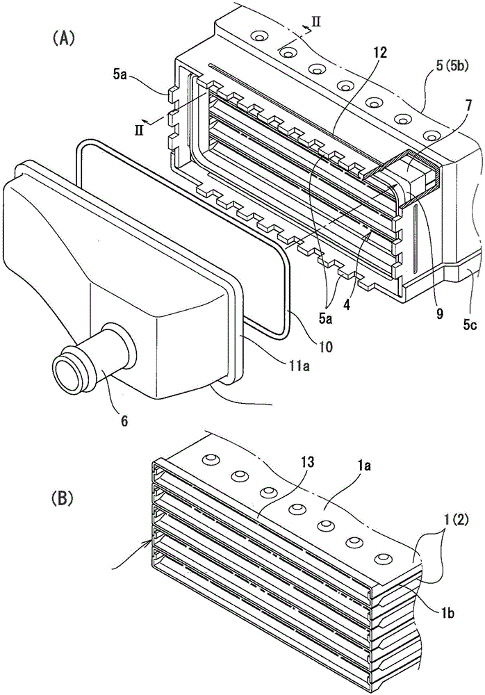
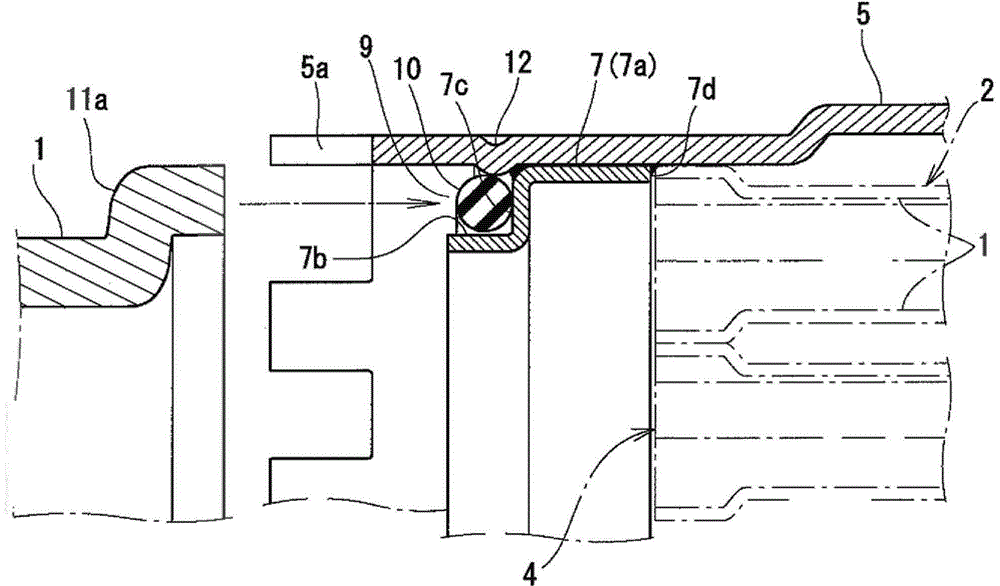
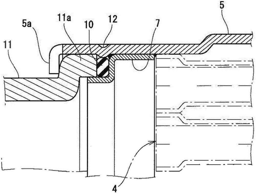
[0081] This heat exchanger has a core 4 composed of a laminated body of a plurality of flat tubes 2, a shell 5 covering the outer periphery of the core 4, a tank support 7 connected to the inner periphery of the end of the shell 5, a seal 10, and a tank. Subject 11.

[0082] Such as figure 1 As shown in (B), in each of the flat tubes 2 constituting the core 4 , a pair of groove-shaped plates 1 have their groove bottoms 1a facing each other, and their side walls 1b are fitted into each other. Moreover, the bulging part 3 which bulges outward in the groove bottom direction is provided in both opening end parts.

[0083] The respective flat tubes 2 form a core 4 by contacting each other with their bulging parts 3 and being laminated. The first fluid flows through the flat tubes 2 of the core 4 , and the second fluid flows through the gaps between the flat tubes 2 .

[0084] The case ...


PUM


Abstract

The invention provides a tank connecting structure of a no-header plate heat exchanger; and in the no-header plate heat exchanger, a tank body and a shell are connected through riveting. Multiple clamping fixed jaws (5a) are projected at the end outer periphery of the shell (5); a tank support part (7) is arranged at the end inner periphery of the shell (5); an annular groove part (9) is formed between the tank support part (7) and the end of the shell (5), and in this place, a small flange part (11a) of the tank body (11) is embedded by spacing from a sealing piece (10); and the fixed clamping jaws (5a) of the shell (5) are bent to form the tank connecting structure.

Description

technical field [0001] The present invention relates to a connection structure between a shell of a heat exchanger without a header plate and a tank, and relates to a structure in which the connection is performed by riveting. Background technique [0002] Patent Document 1 below describes a heat exchanger that does not have a header plate. [0003] In this heat exchanger, a core is formed from a stack of a plurality of flat tubes, the outer periphery of the core is covered with an outer shell, and a pair of tanks are provided at both ends of the outer shell. Furthermore, cooling water is guided into the housing to circulate around the outer peripheries of the flat tubes, and heating fluid is circulated in the respective flat tubes to perform heat exchange between the two fluids. [0004] This heat exchanger is characterized in that each flat tube is formed by a fitting body of a pair of groove-shaped plates, both ends of the flat tube bulge in the thickness direction, and ...

Claims


Application Information

Patent Timeline
IPC IPC(8): F28F9/26
Inventor 大久保厚文后卓也坂井耐事
Owner T RAD CO LTD
Why Eureka
Try Eureka