Automatic detection system for ball cage holder

An automatic detection and cage technology, which is applied in the direction of measuring devices, instruments, and optical devices, can solve the problems of low automation, low detection accuracy, and low detection efficiency, and achieve simple and reliable mechanisms, high detection accuracy, and improved The effect of utilization

Active Publication Date: 2015-09-09
ZHEJIANG UNIV OF TECH
View PDF6 Cites 6 Cited by
  • Summary
  • Abstract
  • Description
  • Claims
  • Application Information

AI Technical Summary

Problems solved by technology

[0006] The purpose of the present invention is to provide an automatic detection system for ball cages to solve the problems of low automation, low detection accuracy and low detection efficiency of the existing detection mechanism

Method used


Image

  • Automatic detection system for ball cage holder
  • Automatic detection system for ball cage holder
  • Automatic detection system for ball cage holder

Examples


Embodiment Construction

[0026] Below in conjunction with accompanying drawing and embodiment the present invention will be further described:

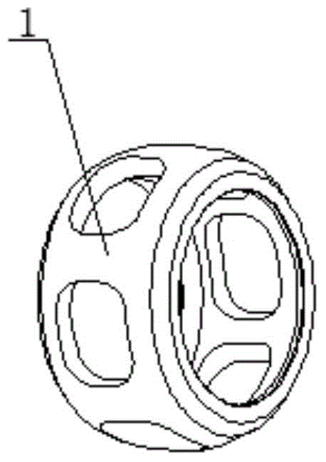
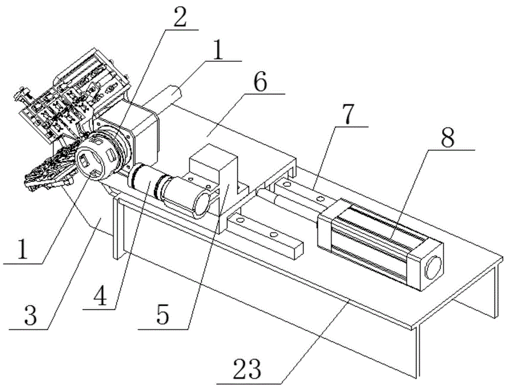
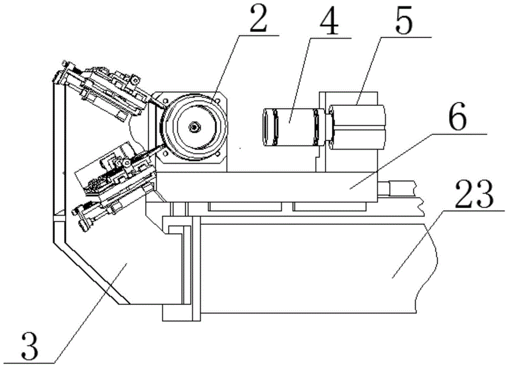
[0027] See attached figure 1 , 2 , 3, 4, 5, 6, an automatic detection system for ball cage cages,

[0028] Including frame 23, suction cup 2, measuring head support 3, camera 4, camera support 5, slide seat 6, slide rail 7, slide seat cylinder 8, measuring tools and main control machine.

[0029] The frame 23 is fixedly connected with the slide rail 7, the slide seat 6 is sleeved on the slide rail 7, and one end thereof is connected with the cylinder rod of the slide seat cylinder 8 fixed on the frame 23, Sliding along the slide rail 7 under the action of the slide cylinder 8; the measuring head bracket 3 is fixed on the end face of the frame 23 near the side of the sliding seat 6, and two measuring tools are fixed on the measuring head bracket 3; the sliding base The camera bracket 5 is installed on the side near the cylinder on the 6, and the camera brac...


PUM


Abstract

The invention discloses an automatic detection system for a ball cage holder, and the system comprises a rack, a sucking disc, a measuring head support, a camera, a camera support, a sliding seat, a sliding rail, a sliding seat cylinder, measuring tools, and a main control machine. During measurement, the sucking disc absorbs the holder, and the sliding seat cylinder pushes the sliding seat to enable the holder to move to a measurement position. The holder is positioned in a movement process, and the two measuring tools achieve one-time precision measurement. Meanwhile, the camera also achieves the precision detection of the holder. Afterwards, the sliding seat cylinder pushes the sliding seat to enable the holder to be separated from the measuring jaws of the two measuring tools. A sucking disc transmission device drives the holder to rotate twice, and the camera achieves the precision detection of the distance between two adjacent holes of the holder. The above process is carried out twice, thereby completing the detection of the holder.

Description

technical field [0001] The invention relates to the technical field of cage accuracy detection, in particular to an automatic detection system for a ball cage cage. Background technique [0002] The cage partially wraps all or part of the rolling elements and moves with them to isolate the rolling elements, guide the rolling elements and keep them in the bearing. For cages on equipment with high speeds such as automotive transmissions, the requirements for dimensional accuracy are very high. If the dimensional accuracy of the cage is not up to standard during the production process, installing it on the vehicle will cause excessive wear of the cage, affecting the service life of the ball cage, or driving safety issues. [0003] Such as figure 1 As shown, the ball cage cage involved in the present invention refers to a metal member whose inner and outer surfaces are spherical surfaces formed after turning, both ends are planes, and 6 ball holes are evenly opened on the sphe...

Claims


Application Information

Patent Timeline
Patent Type & Authority Applications(China)
IPC IPC(8): G01B21/16G01B11/14
CPCG01B21/16
Inventor 单晓杭张瑞曹正硕
Owner ZHEJIANG UNIV OF TECH
Why Eureka
Try Eureka