
Vacuum explosion-proof equipment for explosive material Hopkinson bar test

A technology of Hopkinson rods and explosion-proof devices, applied in the direction of material explosion, which can solve the problems of burning, destructive power enhancement, guide rod impact, etc., and achieve the effect of preventing damage

Active Publication Date: 2015-09-09
XIAN MODERN CHEM RES INST
View PDF2 Cites 11 Cited by
  • Summary
  • Abstract
  • Description
  • Claims
  • Application Information

AI Technical Summary

Problems solved by technology

Due to the particularity of energetic materials, they may burn or even explode under impact, which may damage the Hopkinson bar test system and related test devices, and even cause injury to test personnel. Necessary protection is required during the experiment
A steel protective box is reported in the literature "Research on the Compressive Mechanical Properties and Constitutive Relations of an Aluminum-Containing Explosive" (Energetic Materials, October 2007, Volume 15, Issue 5, Page 460), which is mainly used for To prevent the accidental explosion of the test from causing harm to personnel and instruments, but there are two shortcomings: first, in the confined space, the shock wave generated after the explosion of the explosive is reflected many times, its destructive power is enhanced, and it is easy to cause damage to the protective box; Second, the shock wave generated after the explosion of the explosive will have an impact on the guide rod, which is easy to damage the test system

Method used


Image

  • Vacuum explosion-proof equipment for explosive material Hopkinson bar test
  • Vacuum explosion-proof equipment for explosive material Hopkinson bar test
  • Vacuum explosion-proof equipment for explosive material Hopkinson bar test

Examples


Embodiment Construction

[0016] Below in conjunction with accompanying drawing and embodiment the present invention is described in further detail, it should be noted that the present invention is not limited to following specific embodiment, all equivalent transformations carried out on the basis of the technical solution of the present invention are all within the scope of protection of the present invention.

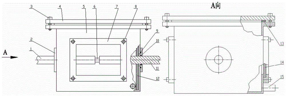
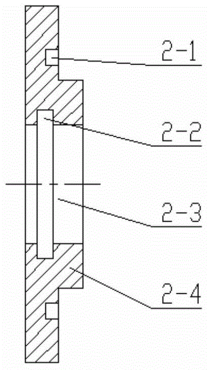
[0017] Such as Figure 1-Figure 5 As shown, this embodiment provides a vacuum explosion-proof device for the Hopkinson rod test of explosive materials, including a transmission rod 1, hexagon socket screws [3, 8], a cover plate 4, an explosion-proof box 5, an explosive sample 6, The incident rod 11 is characterized in that it also includes a rod sleeve 2, a fixed frame 7, a rod sleeve seal ring 9, a rod seal ring 10, a buffer device 12, a cover plate gasket 13, a window cover plate 14, and an air extraction pipe 15. The explosion-proof box 5 is a steel box body. The box body is welded by four...


PUM


Abstract

The invention discloses vacuum explosion-proof equipment for an explosive material Hopkinson bar test. The vacuum explosion-proof equipment comprises a transmission bar, a cover plate, an explosion-proof box, an explosive sample, an incidence bar, bar sleeves, a fixed frame, a bar sleeve sealing ring, a bar sealing ring, a buffering device, a cover plate sealing pad, a window cover plate and an exhaust tube, wherein the explosion-proof box is a box body consisting of front, back, left and right side surfaces and a bottom surface; an opening is formed in the upper end of the box body, and an outer flange is arranged at the opening; a central rectangular opening is formed in each of the front and back side surfaces of the explosion-proof box; a central circular opening is formed in each of the left and right side surfaces of the explosion-proof box; one bar sleeve is mounted in the circular opening in each of the left and right side surfaces of the explosion-proof box; the transmission bar is mounted in a circular through hole of the bar sleeve on the left; the incidence bar is mounted in a circular through hole of the bar sleeve on the right. The vacuum explosion-proof equipment disclosed by the invention is free of impact waves caused by explosion of an explosive material and also can prevent backward movement of an input bar so as to protect a test system.

Description

technical field [0001] The invention belongs to the technical field of propellant and explosive laboratory test devices, and relates to a vacuum explosion-proof device, in particular to a vacuum explosion-proof device suitable for Hopkinson rod tests. Background technique [0002] Explosives must withstand vibration and shock during production, processing, transportation, and storage; when used in armor-piercing, ground-penetrating and other attack weapons, they must withstand dynamic loads with high loading rates; , the impact load of projectiles or fragments, etc. In these processes, the response of explosives firstly manifests itself as a kinetic response, which in turn affects its initiation properties and detonation performance. In order to improve the safety of explosives under different conditions, it is necessary to study the dynamic mechanical properties of explosives under high strain rate dynamic loading. [0003] The Hopkinson rod can measure materials in 10 2...

Claims


Application Information

Patent Timeline
IPC IPC(8): G01N25/54
Inventor 屈可朋许志峰李亮亮周涛王辉肖玮何超
Owner XIAN MODERN CHEM RES INST
Learn More