Stator-winding vacuum water-cooled type non-salient pole generator
A technology of vacuum water cooling and stator winding, applied in the direction of electrical components, electromechanical devices, electric components, etc., can solve the problems of high loss of stator copper winding, high temperature of stator copper winding, large temperature difference along the axial direction, etc., to achieve cost saving, The effect of reducing the heat resistance level requirements and ensuring safe and stable operation
- Summary
- Abstract
- Description
- Claims
- Application Information
AI Technical Summary
Problems solved by technology
Method used
Image
Examples
specific Embodiment approach 1
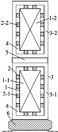
[0018] Specific implementation mode one: combine figure 1 Describe this embodiment mode, the stator winding vacuum water-cooled cathode generator described in this embodiment mode, it comprises stator copper winding 1, stator water pipe 2, stator copper winding insulation 3, vacuum layer 4, interlayer insulation 5 and slot wedge 6 . Stator copper winding 1 is composed of stator upper layer copper winding 1-1 and stator lower layer copper winding 1-2, stator water pipe 2 is composed of stator upper layer water pipe 2-1 and stator lower layer water pipe 2-2, stator copper winding insulation 3 is composed of stator upper layer copper winding Composed of winding insulation 3-1 and stator lower layer copper winding insulation 3-2. The stator water pipe 2 is installed between the stator copper winding 1 and the stator copper winding insulation 3 along the circumferential direction, and the stator water pipe 2 is in close contact with the stator copper winding 1 and the stator copp...
specific Embodiment approach 2
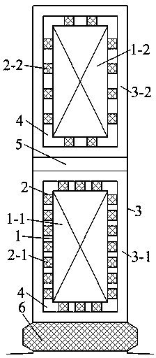
[0021] Specific implementation mode two: combination figure 2 This embodiment is described. The difference between this embodiment and Embodiment 1 is that it increases the number of water pipes 2-1 on the upper layer of the stator, effectively reducing the temperature of the copper windings 1-1 on the upper layer of the stator that generate more serious heat. Other components and connections are the same as those in Embodiment 1.
specific Embodiment approach 3
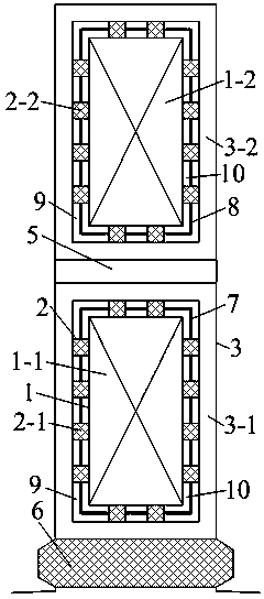
[0022] Specific implementation mode three: combination image 3 Describe this embodiment. The difference between this embodiment and Embodiment 1 is that it installs a heat shield A7 in the middle of the stator upper layer copper winding 1-1 and the stator upper layer copper winding insulation 3-1. The heat shield A7 The thickness is 3 mm-4 mm, which is taken as 3 mm in this embodiment. Install a heat shield B8 at the middle position between the stator lower copper winding 1-2 and the stator lower copper winding insulation 3-2. The thickness of the heat shield B8 is 1 mm-2 mm, which is 1 mm in this embodiment. The area between the heat shield and the stator copper winding insulation 3 is evacuated as an outer vacuum layer 9 and the area between the stator copper winding 1 and the heat shield is evacuated as an inner vacuum layer 10 . After installing the heat insulation board, the heat transfer from the stator copper winding 1 to the stator copper winding insulation 3 can be ...
PUM
 Abstract
Description
Claims
Application Information
 - R&D
- Intellectual Property
- Life Sciences
- Materials
- Tech Scout
- Unparalleled Data Quality
- Higher Quality Content
- 60% Fewer Hallucinations
Browse by: Latest US Patents, China's latest patents, Technical Efficacy Thesaurus, Application Domain, Technology Topic, Popular Technical Reports.
© 2025 PatSnap. All rights reserved.Legal|Privacy policy|Modern Slavery Act Transparency Statement|Sitemap|About US| Contact US: help@patsnap.com


