Laminar flow optional liquid cooler

Inactive Publication Date: 2006-02-14
DELPHI TECH IP LTD
View PDF13 Cites 5 Cited by
  • Summary
  • Abstract
  • Description
  • Claims
  • Application Information

AI Technical Summary

Benefits of technology

[0006]It is thus an object of the present invention to provide a method for limiting the temperature rise between

Problems solved by technology

The majority of the wire length is contained within the center of

Method used


Image

  • Laminar flow optional liquid cooler
  • Laminar flow optional liquid cooler
  • Laminar flow optional liquid cooler

Examples


Embodiment Construction

)

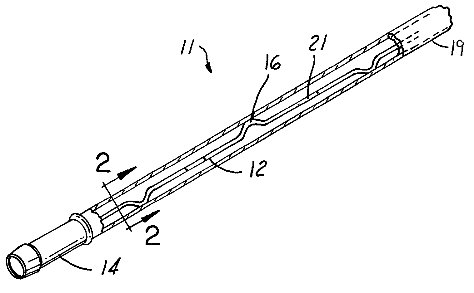
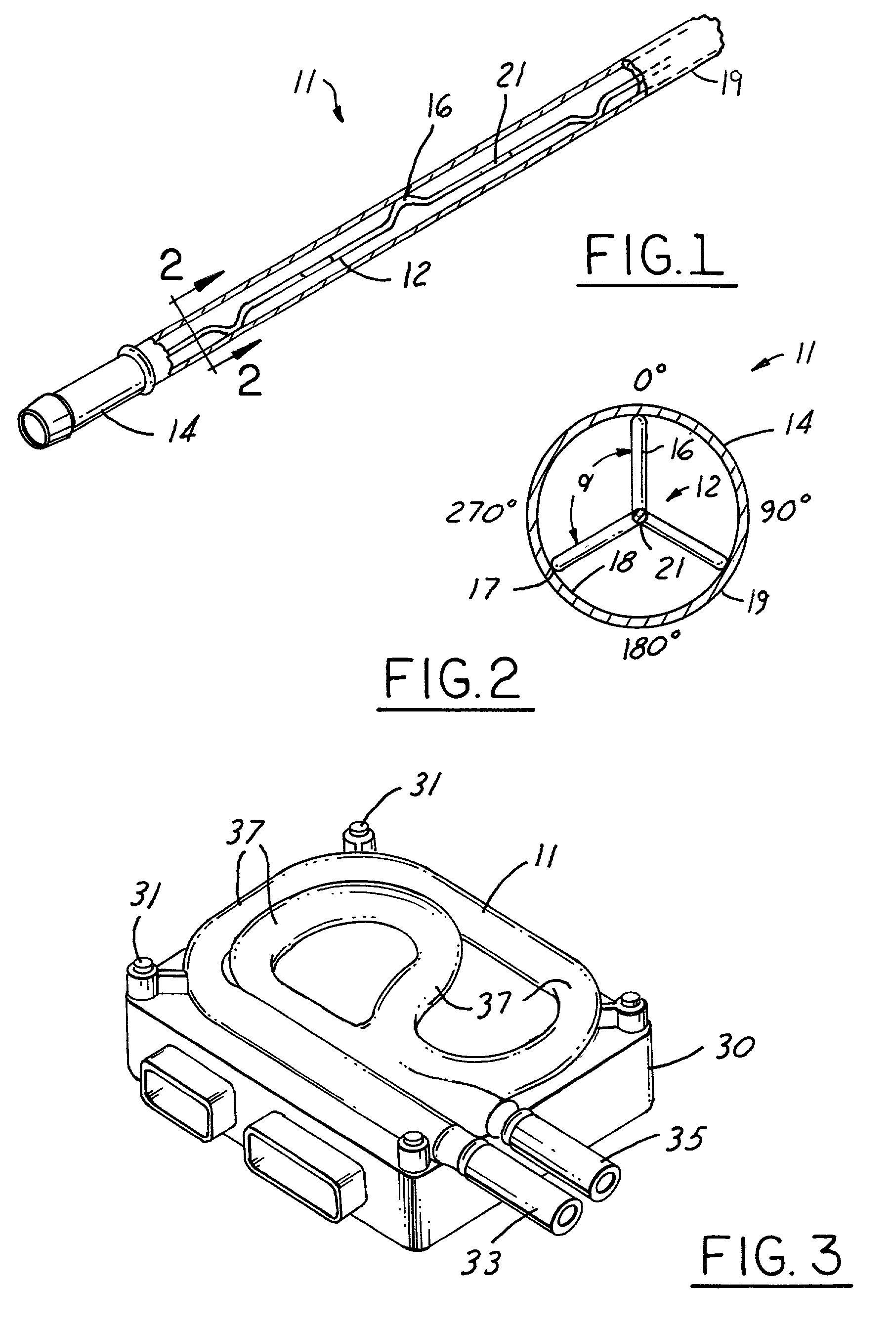
[0021]Referring now to FIG. 1, a liquid cooler 11 according to one preferred embodiment is depicted as having a wire baffle 12 contained within a tube 14. The wire baffle 12 is formed with a minimum of two spaced kink regions 16 situated along its length 1. For a tube 14 approximately ½ inch in diameter, a wire baffle of approximately 0.023 inch diameter having kink regions 16 approximately every 40 millimeters is preferable, although thicker or thinner wires having kink lengths of different sizes are contemplated. Each kink region 16 has an outer lobe region 17 that abuts an inner circular wall portion 18 of the tube 14. The shape of each kink region is preferably oval-shaped, but other smooth shape such as substantially half-circled are contemplated. The tube 14 also has an outer wall 19.

[0022]FIG. 2 illustrates an end view of FIG. 1 showing the wire baffle 12 within the inner circular wall portion 18 of the tube 14. For illustrative purposes, the inner circular wall portion 18 l...


PUM


Abstract

A method and an apparatus for increasing the convective heat transfer capabilities of a liquid cooler coupled to various system and vehicle components. The apparatus includes a structure placed within a hollow tubing of the liquid cooler to distort the laminar flow of fluid within a center portion of the hollow tubing, which decreases the temperature rise of the fluid along an outer wall of the hollow tubing associated with laminar flow. In preferred embodiments, the structure has an elongated baffle wire or an extruded elongated ridge member. The structure allows the outer surface of the tubing to have increased cooling at a particular liquid flow rate. As a result, there is an increase in heat transfer capability to a coupled system or vehicle component.

Description

TECHNICAL FIELD[0001]The present invention relates generally to liquid coolers and more specifically to laminar flow optional liquid coolers.BACKGROUND[0002]Liquid coolers are used to provide accessory liquid cooling to a wide variety of vehicle and system components. Essentially, liquid coolers consist of fluid tubes coupled to a vehicle or system component. The outer surfaces of the fluid tubes provide a surface to remove heat from the vehicle or system component.[0003]In general, liquid flowing through the tubing experiences laminar flow, turbulent flow, or a combination of laminar and turbulent flow. In the context of liquid coolers, laminar flow is fluid flow in which all fluid motion is in the direction of the axis of the tubing, while turbulent flow is fluid flow in which the fluid is tumbling or mixing within the tube.[0004]Consider laminar flow, for example, in a horizontally oriented simple plain tube having a one-half inch diameter and one meter long having diesel flow en...

Claims


Application Information

Patent Timeline
IPC IPC(8): F28F13/12F28F1/40
CPCF28F1/40F28F1/405F28F2255/16
Inventor VISSER, ROY ALAN
Owner DELPHI TECH IP LTD
Why Eureka
Try Eureka