Current-limiting fuse used for protecting ozone high-frequency discharge unit

A high-frequency discharge and fuse technology, which is applied in the field of current-limiting fuses for the protection of ozone high-frequency discharge units, can solve the problems of poor arc extinguishing effect and weak breaking capacity of the fuse, and achieves simple structure and improved opening. The effect of breaking capacity and enhancing performance

Inactive Publication Date: 2016-01-27
DALIAN UNIV OF TECH
View PDF9 Cites 5 Cited by
  • Summary
  • Abstract
  • Description
  • Claims
  • Application Information

AI Technical Summary

Problems solved by technology

[0035] The purpose of the present invention is to propose a current-limiting fuse for ozone high-frequency discharge unit protection, which can effectively cut off the fault current, in view of the shortcomings of the above-mentioned

Method used


Image

  • Current-limiting fuse used for protecting ozone high-frequency discharge unit
  • Current-limiting fuse used for protecting ozone high-frequency discharge unit
  • Current-limiting fuse used for protecting ozone high-frequency discharge unit

Examples


Embodiment 1

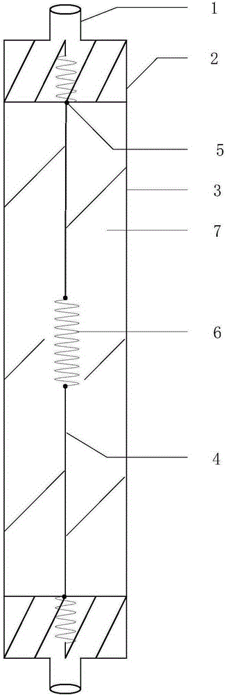
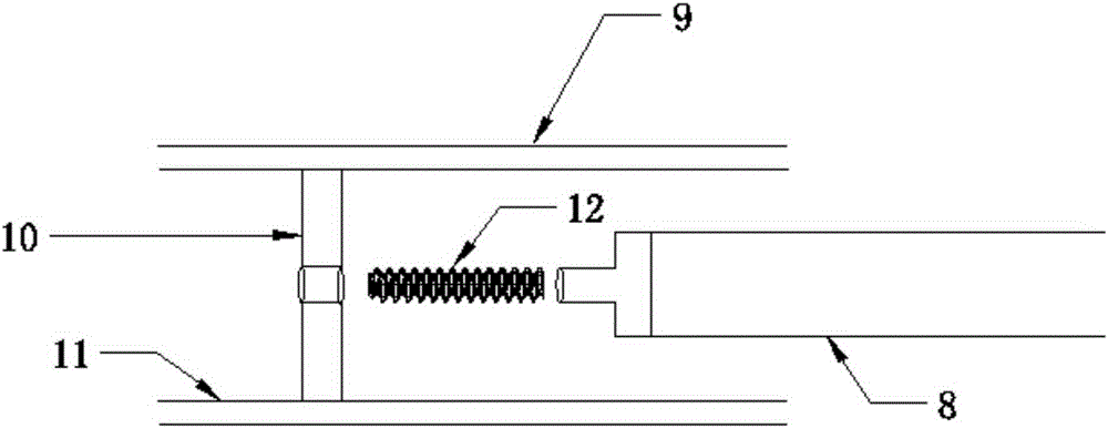
[0058] This embodiment discloses a current-limiting fuse for ozone high-frequency discharge unit protection that can cut off the circuit in time in a fault state. Its structure is as follows: figure 1 Shown; Also disclose the structure of part reactor electrode at the same time, as image 3 shown. It includes a cylindrical housing 3 which is an epoxy resin tube. The two ends of the cylindrical shell 3 are respectively compressed by the copper caps 2. Nuts 1 are arranged on the two copper caps 2. The inner side of the nut 1 has a screw thread that cooperates with the screw rod 12. The nut 1 is connected to the ozone reaction through the screw rod. The copper rod 10 in the reactor is connected, and the copper rod 10 is connected to the reactor electrode 11. The length of the housing 3 is determined according to the minimum length of the fuse tube. The length of the fuse tube is 240 mm. The cross section of the housing is selected according to the requirements of mechanical st...

Embodiment 2

[0079] This embodiment discloses a current-limiting fuse for ozone high-frequency discharge unit protection that can cut off the circuit in time in a fault state. Its structure is basically the same as that of Embodiment 1. The difference is that the housing of this embodiment is a ceramic tube. And because the position of the electrodes inside the reactor is different, considering the insulation problem, the length of the fuse needs to be changed, that is, the length of the melt and the shell should be adjusted appropriately. The shell is 260 mm long, 18 mm in outer diameter, and 2.5 mm thick. The melt is 65mm long and 0.09mm in diameter. The filling rate of quartz sand is 92%.

Embodiment 3

[0081] This embodiment discloses a current-limiting fuse for ozone high-frequency discharge unit protection that can cut off the circuit in time in a fault state. A melt unit, the shell is filled with quartz sand; the melt unit includes a melt, and the melt is provided with a metal or an alloy with a lower melting point than the melt. The melt is simple copper, and the metal whose melting point is lower than that of the melt is tin.


PUM

PropertyMeasurementUnit
Lengthaaaaaaaaaa
Outer diameteraaaaaaaaaa
Thicknessaaaaaaaaaa

Abstract

The invention provides a current-limiting fuse used for protecting an ozone high-frequency discharge unit. The current-limiting fuse comprises a shell body provided with copper caps on both ends, a fuse body unit communicated with the two copper caps is arranged inside the shell body, the shell body is filled with quartz sand, the fuse body unit comprises a fuse body, and metal or alloy with a fusing point lower than that of the fuse body is arranged on the fuse body. The current-limiting fuse is simple, reasonable and compact in structure, enhances the connecting/disconnecting capacity by adopting a design of combining metallurgical effects with multiple fractures, enhances arc extinguishing capacity of the fuse by adopting the quartz sand for filling and connecting springs in tensional state at both ends of the fuse body, and achieves the current-limiting protective function of cutting off a circuit at the fracture under a high current fault and directly cutting off the circuit by the fuse body under a short circuit fault. The current-limiting fuse has high connecting/disconnecting capacity and good arc extinguishing capacity, and can effectively avoid the risk of damaging an ozone generator due to faults such as overcurrent and short circuit by arranging the current-limiting fuse on one side of the discharge unit of the ozone generator.

Description

technical field [0001] The invention relates to fuse technology, in particular to a current-limiting fuse for ozone high-frequency discharge unit protection. Background technique [0002] Ozone is generated by using dielectric barrier discharge technology to ionize oxygen under high pressure conditions, and then synthesize ozone molecules from oxygen atoms and oxygen. Dielectric barrier discharge belongs to corona discharge. During the discharge process, the gas is partially ionized and emits a light blue glow product. [0003] A large ozone reactor is composed of multiple discharge units, and each discharge unit requires a high manufacturing process. According to the experimental analysis, the active current of a single discharge unit is not large when it is working normally. If there is a fault such as overcurrent or short circuit, and it is not cut off in time, it will not only affect the working status of a single discharge unit, but also affect the working status of th...

Claims


Application Information

Patent Timeline
IPC IPC(8): H01H85/05H01H85/11H01H85/36C01B13/11
CPCH01H85/05C01B13/11H01H85/11H01H85/36
Inventor 刘钟阳周伟
Owner DALIAN UNIV OF TECH
Why Eureka
Try Eureka