Liquid crystal display device and method of making the same

a technology of liquid crystal display and liquid crystal panel, which is applied in the direction of printed circuits, circuit thermal arrangements, instruments, etc., can solve the problems of local changes in the performance of the liquid crystal panel, degradation of display quality, and increase the load so as to reduce the temperature rise of the driver ic, suppress the increase of manufacturing cost, and good heat conductive characteristics

Active Publication Date: 2007-07-26
NEC LCD TECH CORP
View PDF4 Cites 6 Cited by
  • Summary
  • Abstract
  • Description
  • Claims
  • Application Information

AI Technical Summary

Benefits of technology

[0018]The liquid crystal display device having one or more driver ICs mounted on a glass substrate of the liquid crystal panel is provided with a heat dissipation pattern of good heat conductive characteristic at locations adjacent to the driver ICs, thereby exhibiting following practical advantages:
[0019]A first advantage is to restrict temperature rise of the driver ICs while suppressing increase of manufacturing cost. This is because a heat dissipation pattern having better heat conductive performance than the glass substrate constituting the liquid crystal panel is formed adjacent to the driver ICs or the heat dissipation pattern is connected to adjacent driver ICs, thereby dissipating the heat generated by the driver ICs.
[0020]A second advantage is to suppress degradation of display quality due to display irregularity or the like as a result of localized heat generation of the liquid crystal panel. This is because thermal distribution of the liquid display panel is made uniform between locations adjacent to and distant from the driver ICs.

Problems solved by technology

As liquid crystal panels become larger, there encounters such problems as increasing loads of driver ICs and heat generated in such driver ICs due to increased power consumption.
Generation of heat by the driver ICs leads to poor display quality due to different heat distribution between locations of the liquid crystal panel adjacent to the driver ICs and distant from such driver ICs, thereby causing local changes in performance of the liquid crystal panel and ultimately degradation in display quality.
Moreover, increased heat generated by the driver ICs causes de-rating of the driver ICs and poor reliability of the driver ICs.
However, even the technologies as disclosed in the first and second references require additional members for enhancing heat dissipation, thereby resulting in cost increase.
Such additional step in the manufacturing process results in increased cost of the product.

Method used


Image

  • Liquid crystal display device and method of making the same
  • Liquid crystal display device and method of making the same
  • Liquid crystal display device and method of making the same

Examples


first embodiment

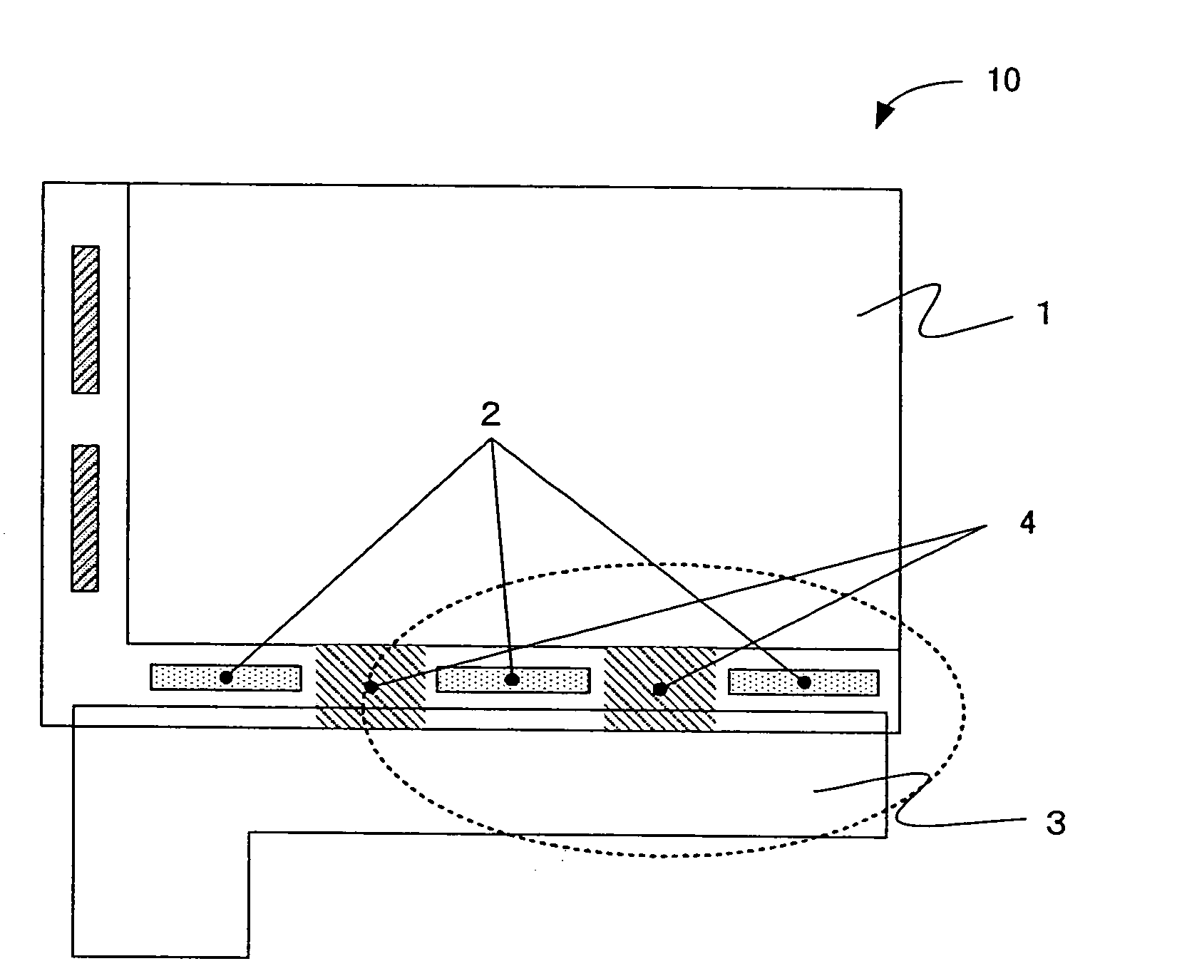
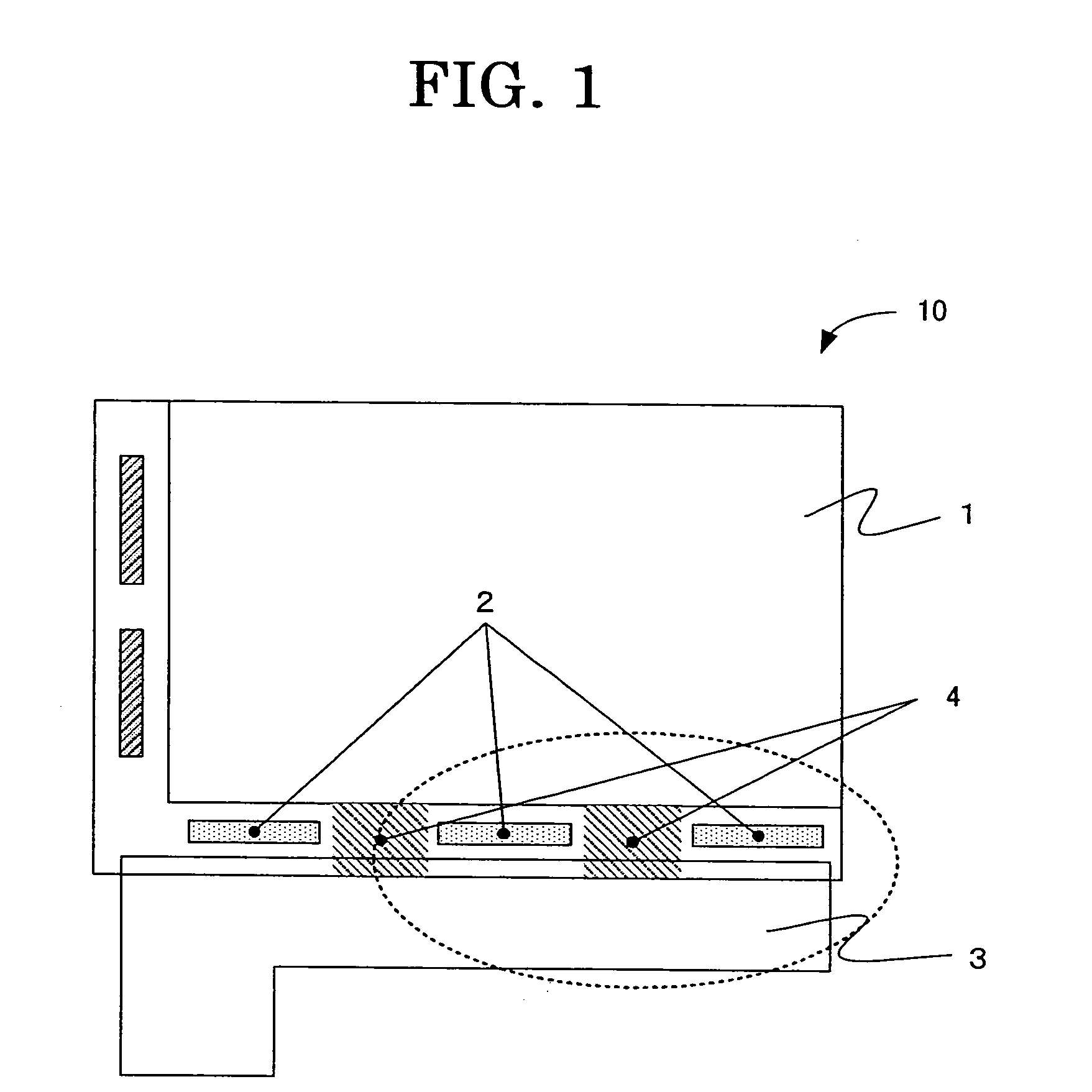
[0034]FIG. 2 is a first embodiment showing in a magnified scale apart adjacent to the driver ICs 2 as shown in FIG. 1. As shown in FIG. 2, the heat dissipation pattern 4 is formed in such a manner to connect or couple adjacent driver ICs 2 and also to the FPC 3.

[0035]Now, the operation of the liquid crystal display device 10 as shown in FIGS. 1 and 2 will be described. In the operating condition of the liquid crystal display device 10 as shown in FIG. 1, the driver ICs 2 are driven and generate heat, thereby raising temperature of the driver ICs 2 as well as the areas adjacent to the driver ICs 2. The heat generated by the driver ICs 2 is conducted to the nearby heat dissipation pattern 4 connected thereto and also conducted to the FPC 3 by way of the heat dissipation pattern 4. Generally, the FPC 3 has a large area of a metal pattern of excellent thermal conductive characteristic, thereby acting as an effective heat dissipation member.

[0036]As apparent from the above description, t...

fourth embodiment

[0042]FIG. 5 is a fourth embodiment showing in a magnified scale a part adjacent to the driver ICs 2 as shown in FIG. 1. As shown in FIG. 5, although the heat dissipation pattern 4 is formed adjacent to the driver ICs 2 similar to the embodiment as shown in FIG. 2, it is not connected to the FCP 3 unlike FIG. 2 but is connected to the adjacent driver ICs 2.

[0043]Although the heat dissipation patterns 4 of the embodiments as shown in FIGS. 3 to 5 exhibit less effective heat dissipation performance as compared to that of the first embodiment, formation of the heat dissipation pattern 4 of good thermal conductive performance adjacent to the driver ICs 2 is effective to achieve more uniform thermal distribution between the driver ICs 2 as compared to prior art in which no heat dissipation pattern is formed. As a result, they are effective to reduce degradation of display quality such as display irregularity or the like due to localized heat generation of the liquid crystal panel 1.

[0044...


PUM

PropertyMeasurementUnit
thermally conductiveaaaaaaaaaa
heat conductive electrically conductiveaaaaaaaaaa
heataaaaaaaaaa

Abstract

Disclosed are a liquid crystal display device 10 and a method of making such liquid crystal display device that improves display quality by providing heat dissipation pattern 4 for effectively dissipating heat generated by the driver ICs 2. The heat dissipation pattern 4 is formed on a glass substrate of a liquid crystal panel 1 along one side thereof so as to minimize non-uniform thermal distribution on the liquid crystal panel 1 at locations adjacent to and distant from the driver ICs 2.

Description

FIELD OF THE INVENTION[0001]This application claims benefits of Japanese Patent Application No. 2006-017871 filed on Jan. 26, 2006, the contents of which are incorporated by the reference.[0002]The present invention relates generally to a liquid crystal display device (LCD) and a method of making the same, more specifically to a liquid crystal display device in which driver ICs are mounted on a glass of a liquid crystal panel of such liquid crystal display device.BACKGROUND OF THE INVENTION[0003]A COG (Chip On Glass) technology for a mounting driver IC on a glass of a liquid crystal panel is gaining popularity in compact liquid crystal display panels to be used for cellular phones or the like. However, a plurality of driver ICs are required in case of applying such COG technology to medium or large size liquid crystal display devices.[0004]As liquid crystal panels become larger, there encounters such problems as increasing loads of driver ICs and heat generated in such driver ICs du...

Claims


Application Information

Patent Timeline
Patent Type & Authority Applications(United States)
IPC IPC(8): G02F1/13
CPCG02F1/133385G02F1/1345H05K3/361H05K1/0203G02F1/13454
Inventor YUGE, KAZUYUKI
Owner NEC LCD TECH CORP
Why Eureka
Try Eureka