
Large Synchronous Motor Stator Cooling Structure

A technology of synchronous motor and cooling structure, applied in cooling/ventilation device, shape/pattern/structure of magnetic circuit, shape/pattern/structure of winding conductor, etc., can solve problems such as poor cooling effect and reduce stator tooth temperature, and achieve The effect of preventing breakdown, reducing eddy current loss, and uniform current distribution

Active Publication Date: 2020-04-21
ELECTRIC POWER RESEARCH INSTITUTE OF STATE GRID SHANDONG ELECTRIC POWER COMPANY +1
View PDF4 Cites 0 Cited by
  • Summary
  • Abstract
  • Description
  • Claims
  • Application Information

AI Technical Summary

Problems solved by technology

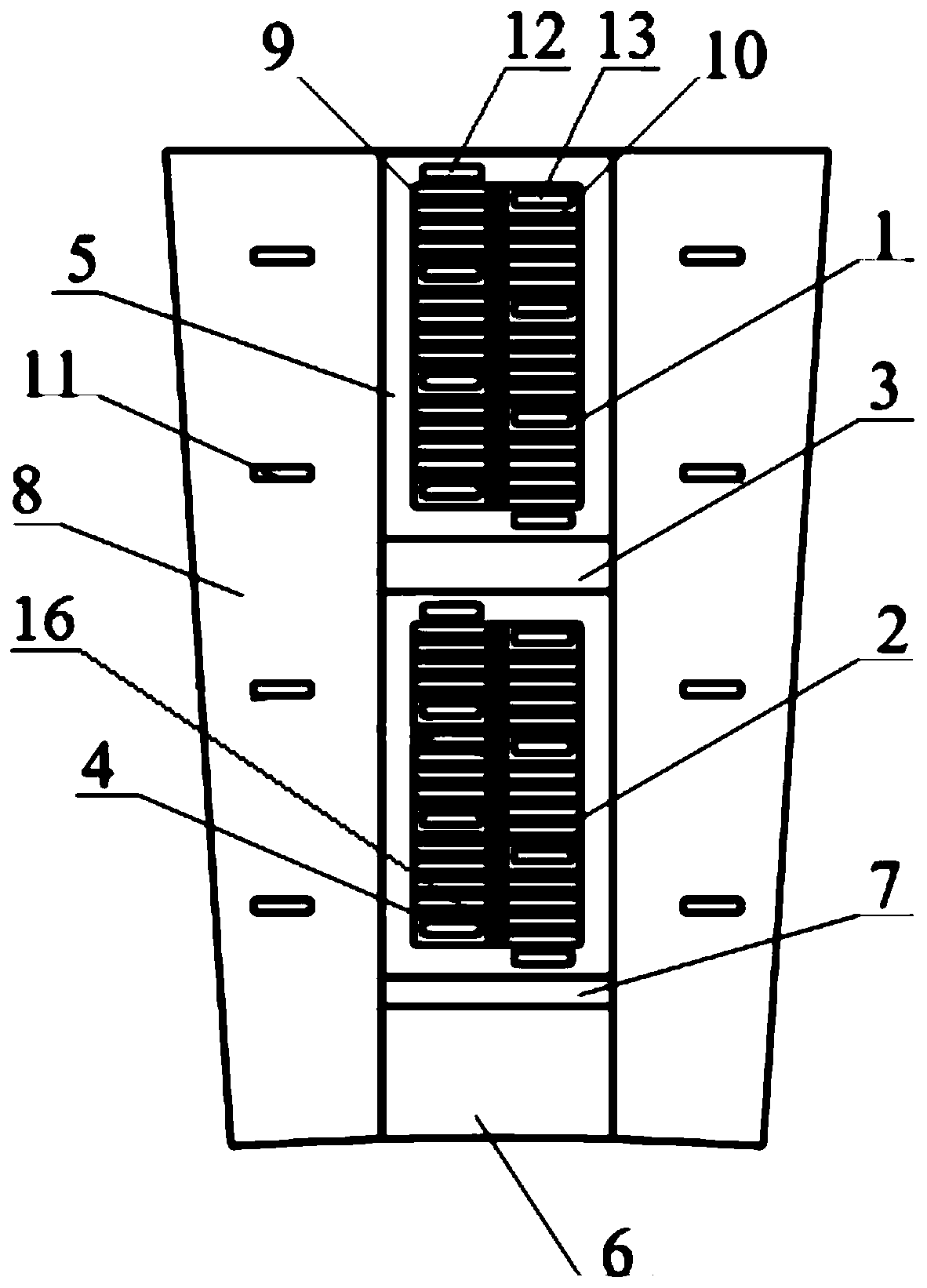
[0004] The present invention is to solve the above-mentioned problems existing in the prior art, and provides a large-scale synchronous motor stator cooling structure; the present invention reduces the temperature of the stator teeth by setting the first water passage on the stator teeth, and passes through the second water passage and the third water passage The synergistic effect reduces the temperature of the upper winding and the lower winding. By setting the first water channel, the second water channel and the third water channel, the stator of the motor is fully cooled, and the cooling effect of the upper layer winding, the lower layer winding and the stator teeth is improved. The motor The stator is fully cooled, which solves the problems of poor cooling effect and serious temperature rise of the existing water internal cooling motor, and improves the safe and stable operation of the motor

Method used


Image

  • Large Synchronous Motor Stator Cooling Structure
  • Large Synchronous Motor Stator Cooling Structure

Examples


Embodiment Construction

[0028] The following will clearly and completely describe the technical solutions in the embodiments of the present invention with reference to the accompanying drawings in the embodiments of the present invention. Obviously, the described embodiments are only some, not all, embodiments of the present invention. Based on the embodiments of the present invention, all other embodiments obtained by persons of ordinary skill in the art without making creative efforts belong to the protection scope of the present invention.

[0029] The purpose of the present invention is to provide a large-scale synchronous motor stator cooling structure to solve the above-mentioned problems in the prior art, so that the stator of the motor can be fully cooled.

[0030] In order to make the above objects, features and advantages of the present invention more comprehensible, the present invention will be further described in detail below in conjunction with the accompanying drawings and specific emb...


PUM


Abstract

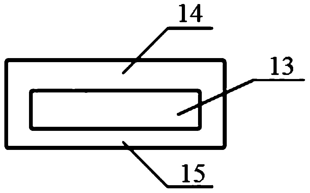
The invention discloses a large synchronous motor stator cooling structure which comprises stator teeth. The stator teeth are provided with a stator slot and first water channels, the first water channels are arranged on two sides of the stator slot, an upper winding and a lower winding are arranged in the stator slot, a layer insulator is arranged between the upper winding and the lower winding,main insulators are arranged on the peripheries of the upper winding and the lower winding, second water channels are arranged on the main insulators, a slot wedge is arranged in the stator slot, a filler strip is arranged between the slot wedge and the lower winding, the upper winding and the lower winding comprise a plurality of rows of braided wires, row insulators are arranged among the braided wires, the braided wires comprise alternate solid conductor groups and hollow conductors, turn-to-turn insulators are arranged among the solid conductor groups and the hollow conductors and among solid conductors inside the solid conductor groups, third water channels are arranged inside the hollow conductors, and cooling media are led into the first water channels, the second water channels andthe third water channels. The cooling effect of the upper winding, the lower winding and the stator teeth is improved, and the safe and stable operation capacity of a motor is improved.

Description

technical field [0001] The invention relates to the technical field of synchronous motors, in particular to a large-scale synchronous motor stator cooling structure. Background technique [0002] Due to the limitations of manufacturing materials and transportation conditions, the volume of large motors cannot be made too large. In order to increase the single-unit capacity of the generator and ensure long-term reliable operation, cooling can only be enhanced while ensuring a compact body structure. When water is used as the cooling medium, it will have a greater heat dissipation capacity than when using gas (such as air, hydrogen) or oil as the cooling medium. In the prior art, large motors mostly use water internal cooling systems. The stator slot of a large motor generally has two upper and lower wire bars, and each wire bar is composed of a solid wire group and a hollow wire, so that part of the heat loss of the solid wire passes through the thin inter-turn insulation an...

Claims


Application Information

Patent Timeline
Patent Type & Authority Patents(China)
IPC IPC(8): H02K1/20H02K3/24H02K3/34H02K9/19
CPCH02K1/20H02K3/24H02K3/34H02K9/19
Inventor 王安东孙福春雍军代海涛曹志伟孙善华王继豪李明庄旭杨敬沫辜超张围围李星
Owner ELECTRIC POWER RESEARCH INSTITUTE OF STATE GRID SHANDONG ELECTRIC POWER COMPANY
Learn More