A method for controlling a SMPC having a synchronous rectification switch, a SMPC and a controller therefor

A synchronous rectification switch and controller technology, applied in control/regulation systems, instruments, output power conversion devices, etc., can solve problems such as unavailability of accuracy

Active Publication Date: 2015-09-09
NXP BV
View PDF8 Cites 16 Cited by
  • Summary
  • Abstract
  • Description
  • Claims
  • Application Information

AI Technical Summary

Problems solved by technology

Such precision may not be available, or only available when usi

Method used


Image

  • A method for controlling a SMPC having a synchronous rectification switch, a SMPC and a controller therefor
  • A method for controlling a SMPC having a synchronous rectification switch, a SMPC and a controller therefor
  • A method for controlling a SMPC having a synchronous rectification switch, a SMPC and a controller therefor

Examples


Embodiment Construction

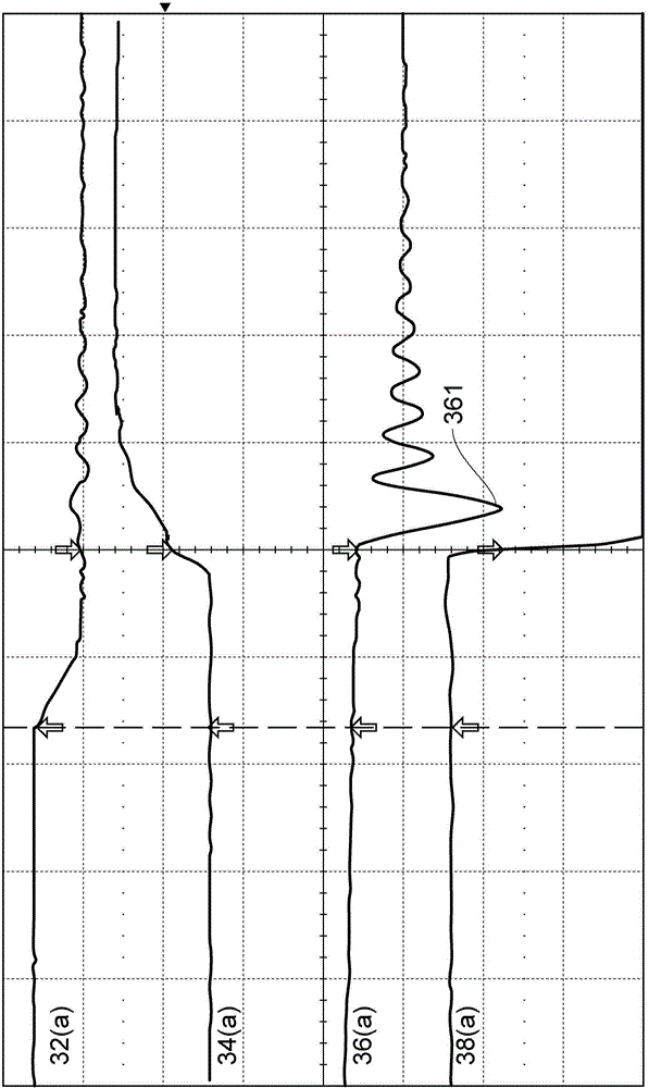
[0037] image 3 , 4 And 5 show the effect of the relative timing of the turning off of the SR switch 16 and the turning on of the primary side switch 13 in the case of continuous conduction mode operation in order to start the primary shock. Curves 32 and 34 show the gate voltage of the SR switch (respectively at 32(a), 32(b), and 32(c)) and the gate voltage of the primary side switch (respectively at 34(a), 34(b)). And 34(c)), such as image 3 Shows the timing of prematurely turning off the SR switch, such as Figure 4 Show the timing of turning off the SR switch at the ideal moment, and as Figure 5 Shows the timing of turning off the SR switch too late. The figure also shows the secondary side current and the primary side switch leakage voltage at 36 and 38 respectively, which are also for the scenarios where the SR switch timing is too early, ideal and too late (respectively corresponding image 3 , 4 And 5).

[0038] Think first image 3 The scenario where the SR switch turn...


PUM


Abstract

A controller for a switched mode power converter is disclosed, the switched mode power converter comprising a transformer defining a primary side circuit and a secondary side circuit, the primary side circuit comprising a primary switch, the secondary side circuit comprising a synchronous rectification switch, the controller comprising: a baseline off-set circuit configured to provide a baseline timing off-set between opening the synchronous rectification switch and closing the primary switch; a peak current detector configured to detect a peak negative current in the secondary side circuit ; and a feedback circuit configured to add an off-set adaptation to the baseline timing off-set to provide an adapted timing off-set, wherein the feedback circuit is configured to adjust the off-set adaptation to minimise the negative peak current. A switched mode power converter and electronic equipment using such a controller is also disclose, as is a method for controlling a switch mode power converter.

Description

Technical field [0001] The invention relates to a switch mode power converter with a synchronous rectification switch in a secondary side circuit, a controller thereof, and a method for controlling the switch mode power converter. Background technique [0002] A flyback converter is a typical example of a switch-mode converter with a transformer or other inductance elements. In the case of a flyback converter, the primary side circuit includes a switch, which can usually be a power MOSFET, switch-type connecting the input power to the primary winding of the transformer. When the switch is turned on (ie, during the primary stroke), current flows through the primary winding; conversely, when the switch is turned off (ie, during the secondary stroke), the current is transferred to the secondary winding of the transformer and Flow into the secondary side circuit, which is usually to charge the capacitor and supply power to the load. A capacitor is usually included in the circuit to...

Claims


Application Information

Patent Timeline
IPC IPC(8): H02M3/335
CPCH02M3/33592Y02B70/10
Inventor 汉斯·哈尔贝施塔特
Owner NXP BV
Why Eureka
Try Eureka