
Camera module and bracket thereof

A technology of camera modules and bumps, which is applied in image communication, TV, color TV parts, etc., and can solve problems such as less glue, inability to firmly connect the voice coil motor and the bracket, and glue flowing to the outer wall of the bracket, etc.

Active Publication Date: 2015-09-09
O FILM IMAGE TECH (GUANGZHOU) CO LTD +4
View PDF7 Cites 7 Cited by
  • Summary
  • Abstract
  • Description
  • Claims
  • Application Information

AI Technical Summary

Problems solved by technology

[0003] In a traditional camera module, the voice coil motor is glued to the mounting surface. After dispensing glue on the mounting surface, the voice coil motor and the bracket are squeezed against each other, and the glue is easily squeezed out completely, resulting in the The amount of glue between the bracket and the bracket is small, and some areas even have no glue, which makes the voice coil motor and the bracket not firmly connected, and it is easy to separate when dropped
There is a lot of glue extruded, even if the overflow groove is set on the edge of the mounting surface, the glue will flow to the outer wall of the bracket, causing the actual size of the bracket to exceed the original design size, that is, the actual size of the camera module Exceeding the original design size, which leads to unqualified dimensions of the camera module

Method used


Image

  • Camera module and bracket thereof
  • Camera module and bracket thereof
  • Camera module and bracket thereof

Examples


Embodiment Construction

[0037] The camera module and its support will be further described below in conjunction with the accompanying drawings and specific embodiments.

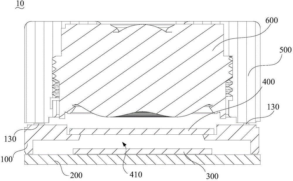
[0038] Such as figure 1 As shown, the camera module 10 of an embodiment includes a bracket 100 , a circuit board 200 , an image sensor chip 300 , an infrared cut filter 400 , a voice coil motor 500 and a lens 600 .

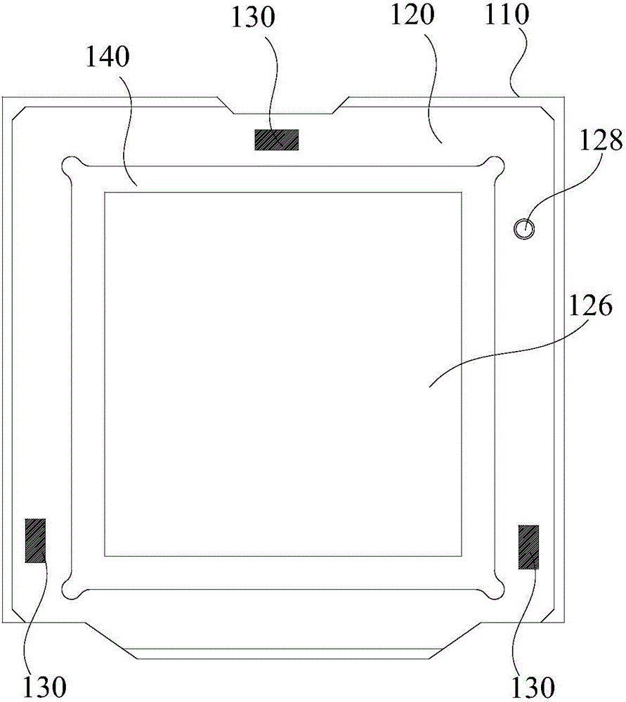
[0039] Such as figure 2 and image 3 As shown, the bracket 100 includes a cylinder body 110 , a mounting plate 120 , a bump 130 and a bearing plate 140 .

[0040] The barrel 100 has a first end surface 112 and a second end surface 114 opposite to each other. In this embodiment, the barrel 100 is square. In other embodiments, the barrel 100 may also be cylindrical.

[0041] The mounting board 120 has a first surface 122 and a second surface 124 opposite to each other. The installation plate 120 is disposed in the cylinder body 110 , and the first surface 122 is flush with the first end surface 112 and constitutes ...


PUM

PropertyMeasurementUnit
Thicknessaaaaaaaaaa

Abstract

The invention relates to a camera module and a bracket thereof. The bracket comprises a barrel, a mounting plate and lugs, wherein the barrel has a first end face and a second end face which are opposite to each other; the mounting plate has a first surface and a second surface which are opposite to each other; the mounting plate is arranged in the barrel; the first surface and the first end face are flush with each other and constructed a mounting surface; the mounting plate is provided with a light hole passing through the first surface and the second surface; the light hole is used for accommodating an infrared cut-off filter of the camera module; the lugs are arranged on the mounting plate; one side of each lug far away from the mounting plate is used for carrying a voice coil motor of the camera module; a plurality of lugs are distributed in such a way that the voice coil motor of the camera module can be erected on the lugs under the condition of no external force; a space between the mounting surface and the lugs far away from the mounting surface is taken as a glue accommodating area; and the second end face is used for connecting a circuit board of the camera module. During assembly of the bracket, the overall dimension of the camera module can be ensured, and the voice coil motor can be prevented from being separated from the bracket in the case of falling.

Description

technical field [0001] The invention relates to the technical field of camera equipment, in particular to a camera module and its bracket. Background technique [0002] A miniature camera module with focusing function usually includes a bracket, an infrared cut filter, a circuit board, an image sensor chip, a lens, and a voice coil motor for realizing the focusing function. The bracket has a light-transmitting hole that runs through its upper and lower surfaces, the infrared cut-off filter is arranged in the light-transmitting hole, the circuit board is arranged at one end of the bracket, and the circuit board, the infrared cut-off filter and the bracket cooperate to form a closed receiving cavity . The image sensor chip is arranged on the circuit board and accommodated in the receiving cavity. The voice coil motor is arranged on the end of the bracket away from the circuit board, the lens is installed in the voice coil motor, and the voice coil motor drives the lens to ex...

Claims


Application Information

Patent Timeline
IPC IPC(8): H04N5/225
Inventor 杨雨丛王昕于立新
Owner O FILM IMAGE TECH (GUANGZHOU) CO LTD
Learn More