
Permanent magnet synchronous traction machine for elevator

A synchronous traction machine and permanent magnet technology, which is applied in the field of traction machines, can solve problems such as difficult to ensure cleanliness, easy oil leakage risks, and potential safety hazards of traction machines

Pending Publication Date: 2020-04-03
HITACHI ELEVATOR GUANGZHOU
View PDF0 Cites 1 Cited by
  • Summary
  • Abstract
  • Description
  • Claims
  • Application Information

AI Technical Summary

Problems solved by technology

[0003] At present, most of the traction machines in the industry have insufficient oil leakage prevention structure design and structural matching. During the long-term operation of the main shaft, there is a risk of oil leakage.
With the rotation of the main shaft and the brake wheel, the leaked oil will flow along the surface of the brake wheel, making it difficult to keep the braking surface of the traction machine clean
However, once there is oil on the braking surface, the braking torque will be insufficient, which poses a serious safety hazard to the operation of the traction machine

Method used


Image

  • Permanent magnet synchronous traction machine for elevator
  • Permanent magnet synchronous traction machine for elevator

Examples


Embodiment Construction

[0022] In order to make the object, technical solution and advantages of the present invention clearer, the present invention will be further described in detail below in conjunction with the accompanying drawings and specific implementation methods. It should be understood that the specific embodiments described here are only used to explain the present invention, and do not limit the protection scope of the present invention.

[0023] It should be noted that when an element is referred to as being “fixed” to another element, it can be directly on the other element or there can also be an intervening element. When an element is referred to as being "connected to" another element, it can be directly connected to the other element or intervening elements may also be present. The terms "vertical," "horizontal," "left," "right," and similar expressions are used herein for purposes of illustration only and are not intended to represent the only embodiments.

[0024] Unless otherw...


PUM


Abstract

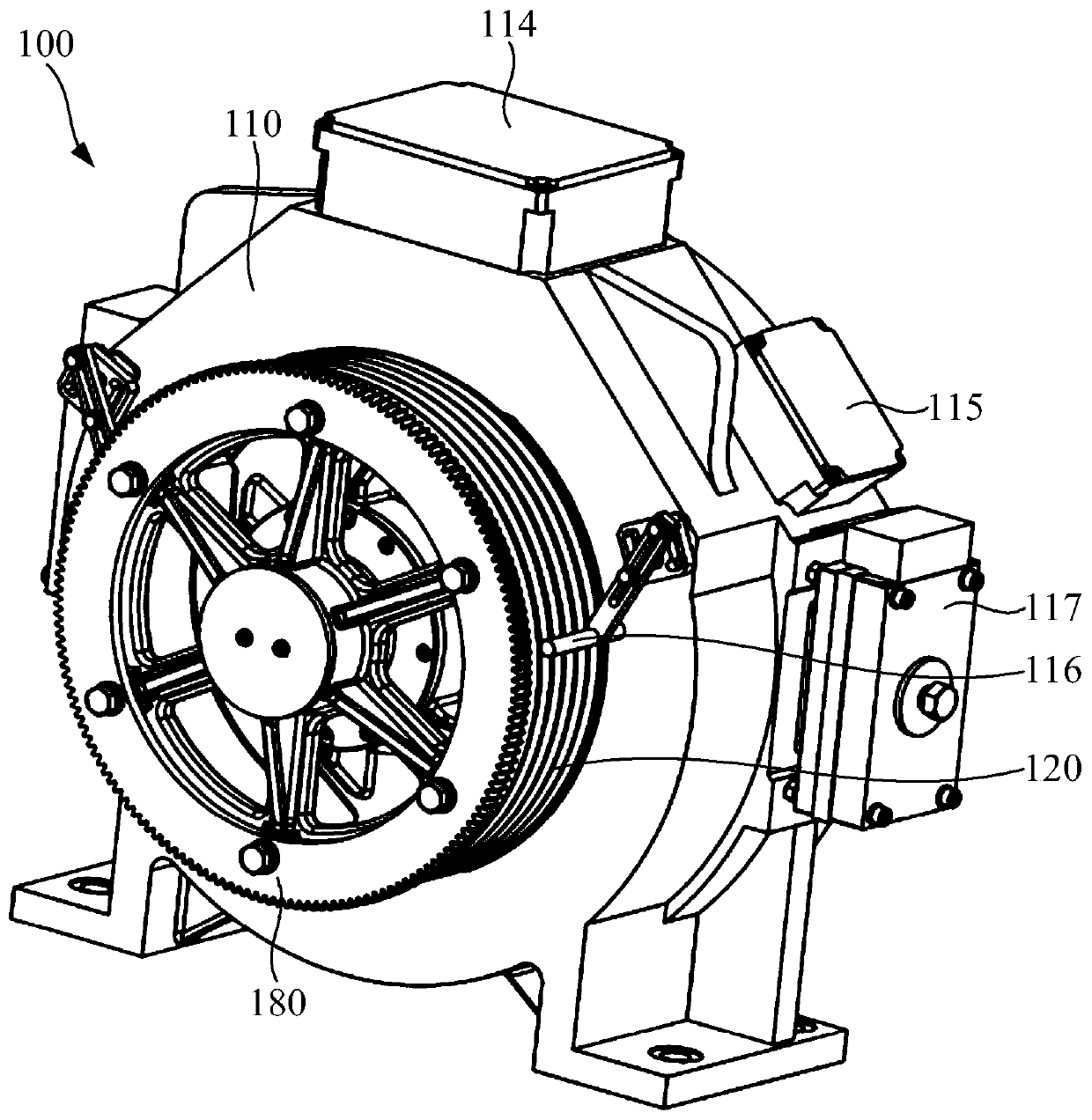
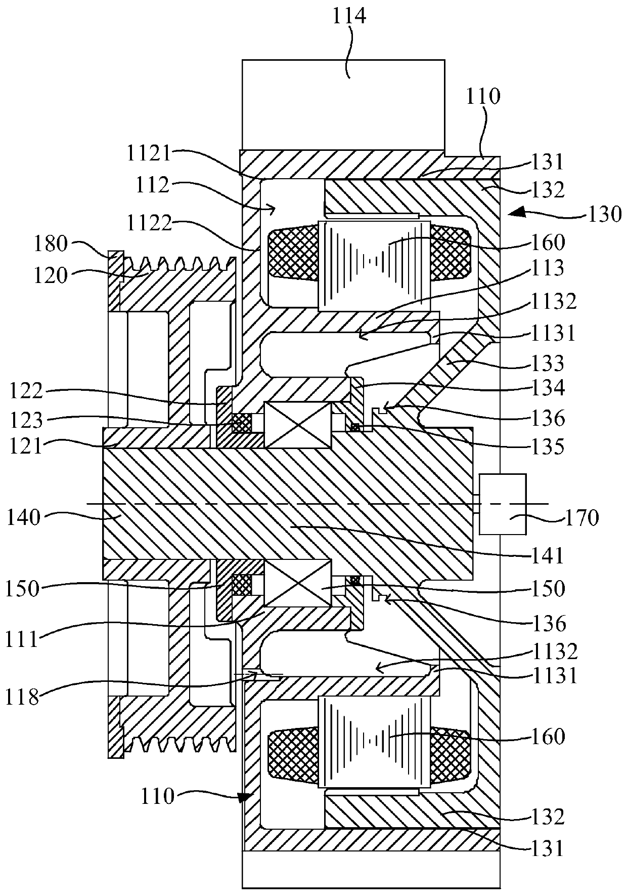
The invention discloses a permanent magnet synchronous traction machine for an elevator, wherein a traction wheel and a brake wheel are connected to a main shaft, and the traction wheel, the brake wheel and the main shaft are synchronously rotated. In this way, through the main shaft, stable torque transmission is realized between the brake wheel and the traction wheel, and stable start-stop operation of the traction wheel is realized. Because the brake wheel is equipped with an oil removal groove at a side towards the bottom of a holding tank and the oil removal groove is disposed in the circumferential direction of the main shaft, the oil removal groove is located between the main shaft and a brake surface and cuts off the flow of oil stain between the main shaft and the brake face. Whena sealing structure on the permanent magnet synchronous traction machine for the elevator fails to operate and leaks oil, the oil stain can flow into the oil removal groove along the inner surfaces of the main shaft and the brake wheel, and loses the power continuously flowing along the inner surface of the brake wheel under the storage effect of the oil removal groove. Thus, the oil stain is effectively prevented from flowing onto the brake surface along the inner surface of the brake wheel under the condition of oil leakage, and the stable output of braking torque is greatly ensured.

Description

technical field [0001] The invention relates to the technical field of traction machines, in particular to a permanent magnet synchronous traction machine for elevators. Background technique [0002] Permanent magnet synchronous traction machine, also known as gearless drive, is used to install in the elevator machine room or in the elevator shaft, generally on the top floor of the building or inside the shaft, and is the power device of the elevator. Permanent magnet synchronous traction machine, the main engine directly drives the sheave, without gear box device. With the rapid development of the elevator market, the application of permanent magnet synchronous traction machines is increasing, accounting for more than 70% of all elevator traction machines. [0003] At present, most of the traction machines in the industry have insufficient oil leakage prevention structure design and structural matching. During the long-term operation of the main shaft, there is a risk of o...

Claims


Application Information

Patent Timeline
IPC IPC(8): B66B11/04B66D1/36B66D5/06F16N31/00H02K1/27H02K7/102
CPCB66B11/0438B66D1/36B66D5/06F16N31/00F16N2210/18H02K1/2786H02K7/102Y02B50/00
Inventor 詹奉明谢喜金郑美珠
Owner HITACHI ELEVATOR GUANGZHOU
Learn More