Thread guide unit, motion damper for a thread guide unit, and method for producing the motion damper

A technology of buffers and wire guides, which is applied in the directions of transportation and packaging, friction dampers, and delivery of filamentous materials, etc. It can solve the problems of short maintenance or repair intervals of wire guide units and unfavorable service life of traction mechanisms, etc., to achieve Effects of improved service life, simple manufacture, and increased surface pressure

Active Publication Date: 2015-09-09
SSM萨罗瑞士麦特雷有限公司
View PDF10 Cites 4 Cited by
  • Summary
  • Abstract
  • Description
  • Claims
  • Application Information

AI Technical Summary

Problems solved by technology

This is detrimental to the service life of the traction mechanism and often make

Method used


Image

  • Thread guide unit, motion damper for a thread guide unit, and method for producing the motion damper
  • Thread guide unit, motion damper for a thread guide unit, and method for producing the motion damper
  • Thread guide unit, motion damper for a thread guide unit, and method for producing the motion damper

Examples


Embodiment Construction

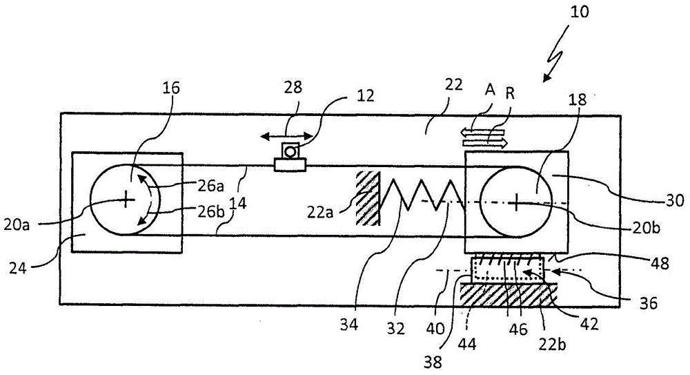
[0034] figure 1 The thread guide unit 10 is shown with a thread guide 12 which is fastened to a cable-like pulling mechanism 14 . The traction element 14 surrounds a deflection roller 16 and a tensioning roller 18 , which are mounted rotatably about an axis of rotation 20 a , 20 b in each case on a plate-shaped support 22 of the thread guide unit 10 . As shown in the figure, the traction means 14 can be designed in the form of a ring. The deflection roller 16 can be driven about its axis of rotation 20 a in opposite directions of rotation 26 a , 26 b by a drive motor 24 and thus serves as a drive roller for the traction mechanism 14 . The yarn guide 12 can thus be reciprocated by the pulling mechanism 14 in rapid sequence in the reciprocating direction indicated by the double arrow 28, for example to wind the yarn guided on the yarn guide 12 onto a bobbin (not shown) .

[0035] Such as figure 1As shown, the tensioning roller 18 is mounted displaceably relative to the carri...


PUM

PropertyMeasurementUnit
Thicknessaaaaaaaaaa
Lengthaaaaaaaaaa

Abstract

The thread guide unit (10) has a thread guide (12) and a traction device (14), which is guided around a deflection roller (16) and a tensioning roller (18), where the thread guide is mounted to the traction device. A drive (24) is provided for back and forth movement of the traction device, where a biasing element (34) is provided, by which a clamping position exciting the tension roller in the traction device, is maintained. Damper plates (46) are frictionally applied with their free ends on a friction surface (48) of the thread guide unit. An independent claim is included for a method for producing a motion damper.

Description

technical field [0001] The invention relates to a wire unit, a motion damper for a wire unit and a method for producing the motion damper. Background technique [0002] In the textile industry, in particular in winding machines or rewinding machines, thread guide units are used with rope, belt or stranded wire traction mechanisms to which the thread guides are fixed . The traction means can be moved back and forth in rapid succession by a drive and, in the structurally simplest case, can be guided around at least one deflection roller and a tensioning roller. The tensioning roller is usually arranged on a support, such as a support plate, of the thread guide unit so that it can move in one direction of movement via a slide. The tensioning roller is also pretensioned by a pretensioning roller interacting with the tensioning roller in a tensioning position, which tensions the traction mechanism. During the operation of such a pull-mechanism-based wire guide unit, the pull-m...

Claims


Application Information

Patent Timeline
IPC IPC(8): B65H54/28F16F7/08
CPCB65H54/2821F16F7/08
Inventor E·洛伊
Owner SSM萨罗瑞士麦特雷有限公司
Why Eureka
Try Eureka