Centrifugal fan

A technology of centrifugal fans and hubs, which is applied in non-variable pumps, radial flow pumps, pump components, etc., and can solve problems such as difficulty in utilizing the diffusion effect

Inactive Publication Date: 2015-09-09
DAIKIN IND LTD
View PDF5 Cites 0 Cited by
  • Summary
  • Abstract
  • Description
  • Claims
  • Application Information

AI Technical Summary

Problems solved by technology

Therefore, it is difficult to improve the diffusion effect by using the diffuser rings 126, 127 arranged on the outer peripheries of the hub 115 and the wheel cover 119.

Method used


Image

  • Centrifugal fan
  • Centrifugal fan
  • Centrifugal fan

Examples


Embodiment Construction

[0027] Hereinafter, the indoor unit of the air conditioner according to the embodiment of the present invention will be described in detail with reference to the drawings.

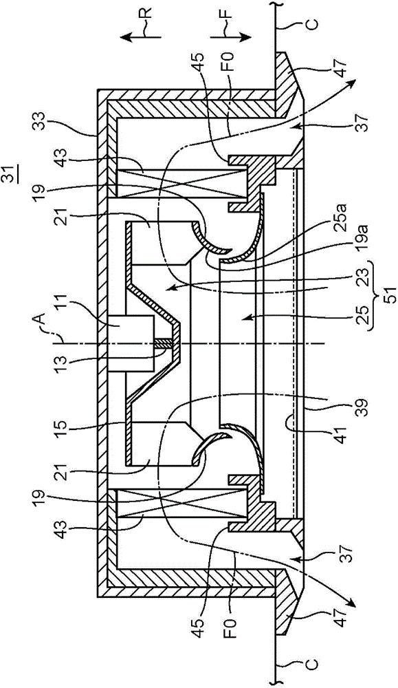
[0028] figure 1 The illustrated indoor unit 31 is a box-type indoor unit of a ceiling-embedded type. The indoor unit 31 includes: a substantially rectangular parallelepiped casing 33 fitted in an opening provided in the ceiling C; and a panel 47 attached to the lower portion of the casing 33 . The shape of the panel 47 in plan view is slightly larger than that of the casing 33 , and is exposed indoors while covering the opening of the ceiling C. As shown in FIG. The panel 47 has a rectangular suction grill 39 provided at the center thereof, and a plurality (for example, four) of elongated rectangular air outlets 37 provided along each side of the suction grill 39 .

[0029] The indoor unit 31 includes: a blower 51 including a centrifugal fan 23 ; a fan motor 11 that drives and rotates the centrifugal fa...


PUM


Abstract

A centrifugal fan (23) is provided with a hub (15), blades (21), and a shroud (19). Each of the blades (21) has a curved section (21d) which is curved so as to be tilted to the side (21c1) on which an air current impinges when the connection end section (21c) where the blade (21) and the portion of the shroud (19) which protrudes inward are joined moves in the rotational direction of the centrifugal fan (23). The hub (15) has a hub-side diffuser ring (27) protruding to the outer peripheral side of the blades (21). The shroud (19) has a shroud-side diffuser ring (26) which protrudes to the outer peripheral side of the blades (21).

Description

technical field [0001] The invention relates to a centrifugal fan. Background technique [0002] Conventionally, in air conditioners and other air conditioners for large-scale air conditioning inside buildings, centrifugal fans such as turbo fans have been used to supply air at high pressure. The turbofan is a fan with blades facing backward, and is configured to blow airflow outward in the radial direction. Therefore, the turbofan has the advantage of being simple in structure without needing a volute like a sirocco fan. However, since the airflow blown out from the vane interferes with objects around the vane and the flow is disturbed, there is a problem of an increase in noise and a decrease in efficiency. [0003] In this regard, conventional turbofans such as those described in Patent Document 1 and Patent Document 2 are equipped with a hub, a plurality of blades arranged in a row in the circumferential direction of the hub, and a shroud arranged on the opposite side ...

Claims


Application Information

Patent Timeline
Patent Type & Authority Applications(China)
IPC IPC(8): F04D29/30F04D29/28
CPCF04D29/281F04D29/30F04D29/288F04D29/441F04D17/10
Inventor 岩田透丸山要郑志明
Owner DAIKIN IND LTD
Why Eureka
Try Eureka