
Rigid suspension system device for overhead contact line

A suspension system and catenary technology, which is applied in the direction of overhead lines, etc., can solve the problems of unsatisfactory busbar sliding smoothness and unreasonable life matching of rigid suspension systems, so as to prevent or reduce sticking phenomenon, reasonable service life of the system, The effect of ensuring driving safety

Inactive Publication Date: 2015-09-16
CHINA CREC RAILWAY ELECTRIFICATION BUREAU GRP +2
View PDF7 Cites 3 Cited by
  • Summary
  • Abstract
  • Description
  • Claims
  • Application Information

AI Technical Summary

Problems solved by technology

[0004] That is to say, the life matching of the current rigid suspension system products is unreasonable, and the connection method may lead to unsatisfactory sliding smoothness of the busbar in some special sections. Therefore, it is necessary to optimize the suspension method of the existing rigid suspension system and improve the suspension system. way, avoid sticking phenomenon, improve the service life of the overall system, and reduce maintenance workload

Method used


Image

  • Rigid suspension system device for overhead contact line
  • Rigid suspension system device for overhead contact line
  • Rigid suspension system device for overhead contact line

Examples


Embodiment 1

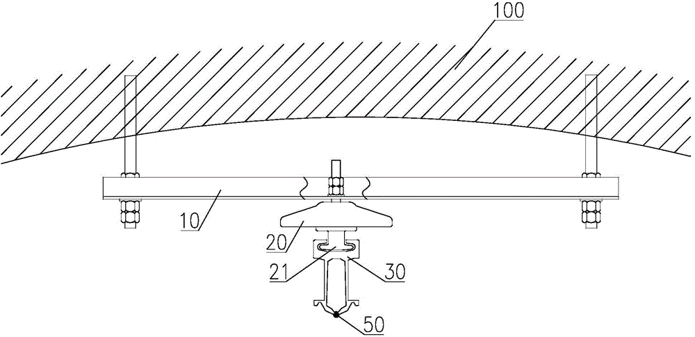
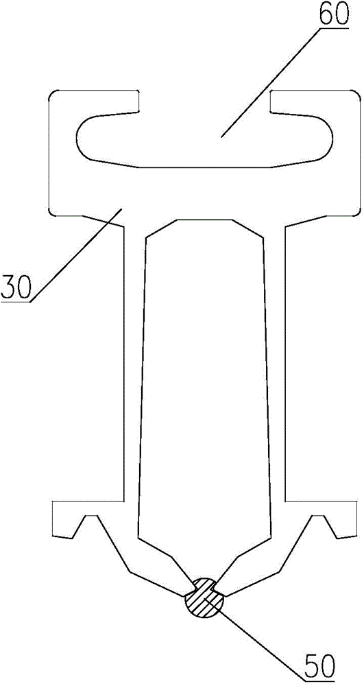
[0027] See figure 1 and figure 2 As shown, the overhead catenary rigid suspension system device includes: a suspension device 10 fixed on the tunnel top 100, an insulator 20 fixed on the suspension device 10, a bus bar 30 suspended on the insulator 20, and The lower part of the bus bar 30 is fixed with a contact wire 50 . Of course, the tunnel top 100 can also be a frame.

[0028] Furthermore, the upper part of the insulator 20 is fixed on the suspension device 10 by M16 and other screws. The lower part of the insulator 20 is provided with a club head type connector 21 . The so-called club head type means that the connecting head 21 is approximately oblate. At the same time, the upper part of the bus bar 30 is provided with a slot 60 , the cross section of which is semi-enclosed with the opening facing upwards, and the connector 21 is stuck in the slot 60 after entering from one end of the slot 60 . Of course, the slot 60 extends along the longitudinal direction of the b...

Embodiment 2

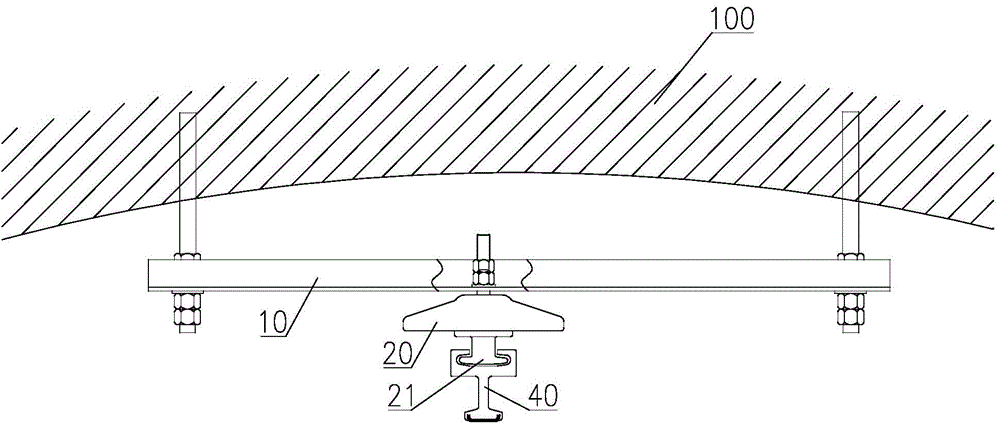
[0032] See image 3 and Figure 4 As shown, the difference from Embodiment 1 is only that: the bus bar 30 is replaced by a contact rail 40, the slot 60 is located on the upper part of the contact rail 40, and the contact wire 50 is fixed to the contact rail by composite or welding process The stainless steel belt 41 of 40 lower parts or aluminum rail replace. In this way, the pantograph-catenary can transition smoothly, receive current stably, and further extend the maintenance cycle.


PUM


Abstract

The invention discloses a rigid suspension system device for an overhead contact line. The rigid suspension system device for the overhead contact line comprises a suspension device fixed to the top of a tunnel, an insulator fixed to the suspension device, and a busbar suspended on the insulator, wherein the contact line is fixed to the lower portion of the busbar, the upper portion of the insulator is fixed to the suspension device through a screw, and a pestle head type connector is arranged on the lower portion of the insulator; meanwhile, a clamping groove is formed in the upper portion of the insulator, the section of the clamping groove is open upwards and is of a semi-surrounding type, and the connector enters the clamping groove from one end of the clamping groove and then is clamped in the clamping groove. The rigid suspension system device for the overhead contact line has the advantages that the probability of getting stuck can be prevented or lowered, a locomotive well receives flow, and traveling safety is guaranteed.

Description

technical field [0001] The invention relates to the technical field of rail transit components, in particular to an overhead catenary rigid suspension system device. Background technique [0002] The existing overhead catenary is divided into flexible catenary and rigid catenary. The rigid suspension system is an urban rail transit power supply method in which the contact wire is clamped in the busbar, and the locomotive takes the current from the top of the track through the pantograph. Rigid suspension system has been widely used in my country's urban rail transit due to its simple structure, convenient installation and small maintenance workload. At the same time, with the expansion of city scale, for some suburban lines, it is necessary to increase the running speed of vehicles and repair them in a maintenance-free state. This puts forward higher requirements for the safety and reliability of the rigid suspension system. [0003] The rigid suspension system relies on ...

Claims


Application Information

Patent Timeline
Patent Type & Authority Applications(China)
IPC IPC(8): B60M1/20B60M1/24
Inventor 李增勤崔莹冀炎柴欢
Owner CHINA CREC RAILWAY ELECTRIFICATION BUREAU GRP
Learn More