Chemical discharge cylinder rotary pouring device

A technology of rotating materials and barrels, which is applied in the directions of packaging, loading/unloading, transportation and packaging, etc. It can solve the problems that the material discharging device cannot be disassembled or removed, the pushing angle is limited, and it is easy to touch chemicals, etc.

Active Publication Date: 2015-09-16
山东品冠新材料有限公司
View PDF7 Cites 9 Cited by
  • Summary
  • Abstract
  • Description
  • Claims
  • Application Information

AI Technical Summary

Problems solved by technology

[0002] In chemical, pharmaceutical and other industries, it is often necessary to mix and process various raw materials. The existing method is to push the discharge cylinder through the cylinder to rotate the discharge cylinder at a certain angle, and pour the raw materials in the discharge cylinder into the mixing cylinder. Pushing, its pushing angle is limited, it can only be rotated by about 90°, and it cannot be adjusted to a larger rotation angle, and the raw materials in the discharge barrel cannot be completely dumped, and the cylinder method is adopted, and the maintenance of the cylinder is troublesome and costly. At the same time, when cleaning the discharge barrel regularly, tools or people can only be cleaned from the top into the discharge barrel, which is very troublesome and inefficient
At the same time, the existing raw material unloading device is generally fixed on a component or a platform, so that the raw material unloading device cannot be disassembled or removed from the component or platform, and cannot be moved as required, and cannot meet flexible and changing production needs
[0003] In addition, the existing discharge cylinder does not have a discharge cylinder fixing device during the process of turning over and unloading, so the operator cannot intervene in the process of unloading, and cannot flexibly control the unloading operation, which affects production efficiency. The cover plate of the barrel needs to be opened and closed manually before discharging, which increases the labor intensity and is easy to touch the chemicals on the cover plate, causing human injury

Method used


Image

  • Chemical discharge cylinder rotary pouring device
  • Chemical discharge cylinder rotary pouring device
  • Chemical discharge cylinder rotary pouring device

Examples


Embodiment Construction

[0027] The specific implementation manners of the present invention will be further described in detail below in conjunction with the accompanying drawings and embodiments. The following examples are used to illustrate the present invention, but are not intended to limit the scope of the present invention.

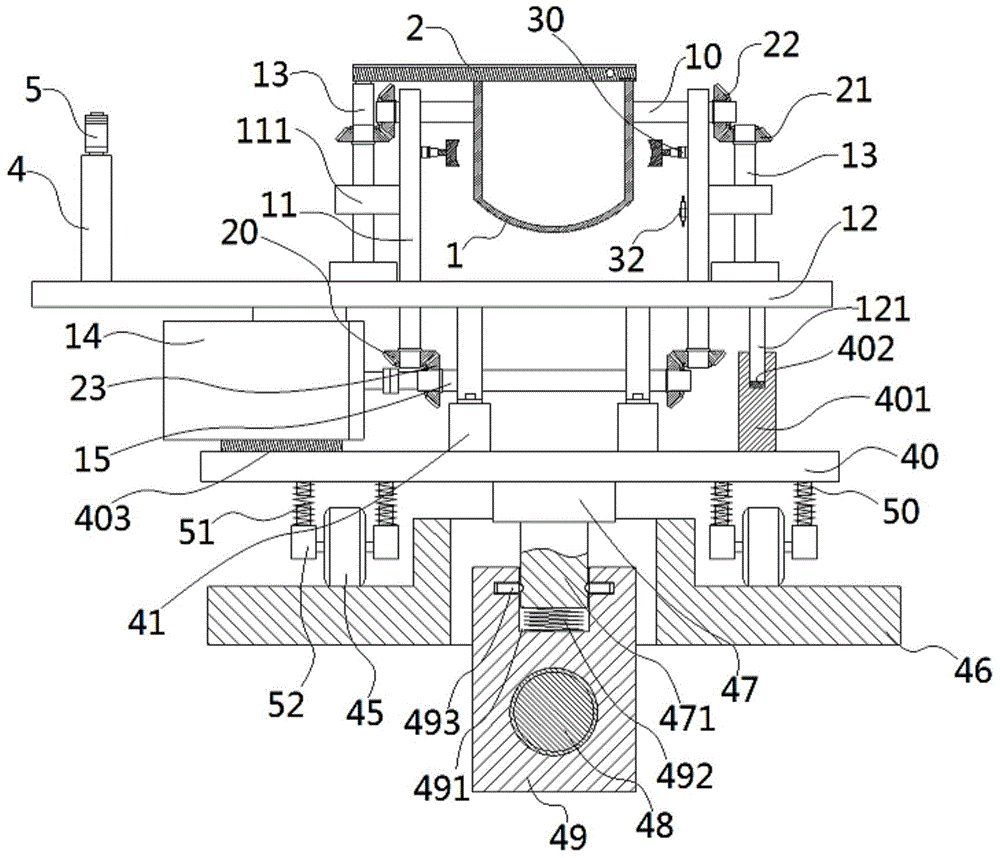
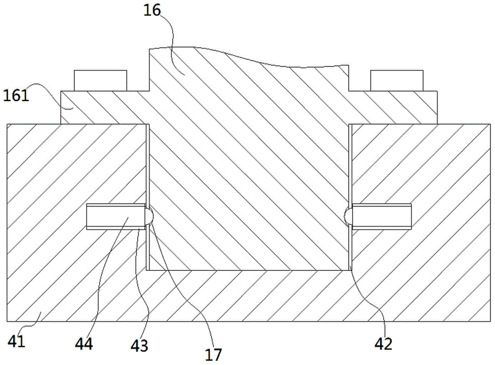
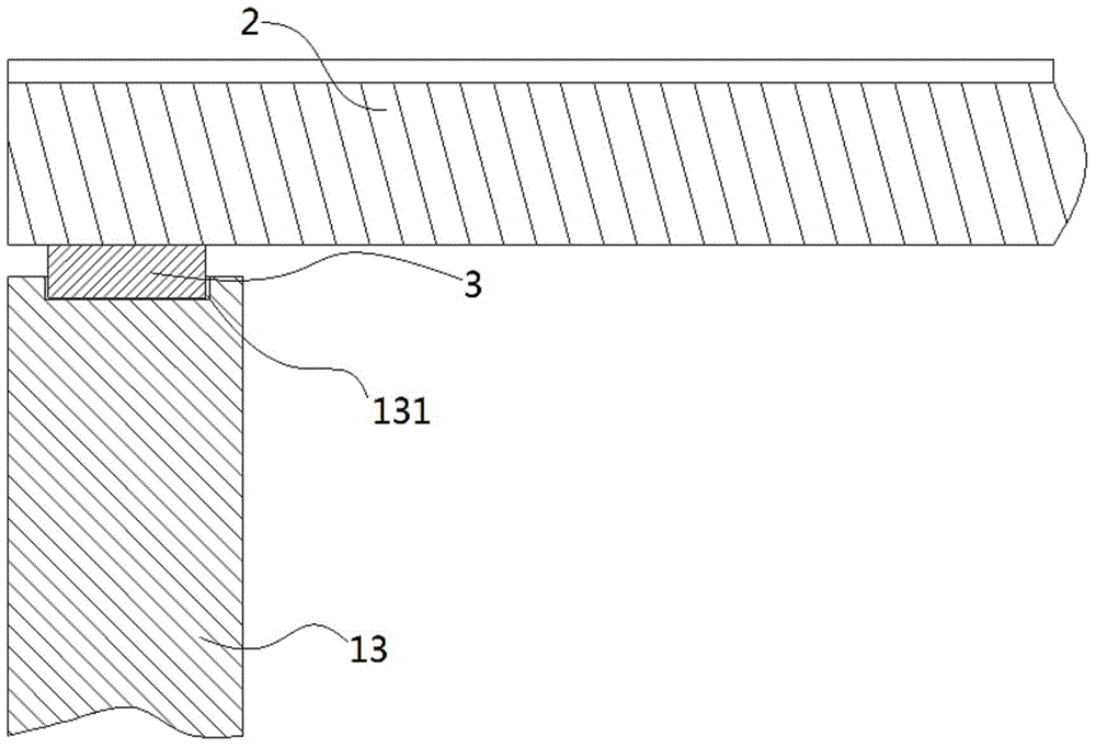
[0028] see Figure 1 to Figure 7 , the chemical discharge cylinder rotary dumping device described in the present invention comprises a discharge cylinder 1 and a cover plate 2 covered on the discharge cylinder 1, two ends of the discharge cylinder 1 are fixed with two rotating Shaft 10, the two rotating shafts 10 are hinged on two support plates 11, the lower ends of the support plates 11 are fixed on the base plate 12, and the base plate 12 is rotatably connected with a vertical rotation rod 13, the vertical The lower end of the rotating rod 13 passes through the base plate 12 and is fixed with a lower bevel gear 20, the upper end of the vertical rotating rod 13 is fixe...


PUM


Abstract

The invention discloses a chemical discharge cylinder rotary pouring device which comprises a discharge cylinder and a cover plate. A rotary shaft is fixed to the discharge cylinder. A vertical rotary rod is connected to a bottom plate. A lower bevel gear is fixed to the lower end of the vertical rotary rod. An upper bevel gear is fixed to the upper end of the vertical rotary rod. A transmission bevel gear is fixed to one end of the rotary shaft. A drive servo motor is fixed to the bottom plate which is connected with a rotary bevel gear. An electromagnet is fixed to the portion, on one side of the discharge cylinder, of a supporting plate. A control shaft of the electromagnet is connected with a clamping block. A discharge cylinder rotary angle sensor is arranged at the portion, on one side of the discharge cylinder, of the supporting plate. At least two connecting plates are fixed to the middle of the bottom face of the bottom plate. A base plate is arranged at the lower portion of the bottom plate. Connecting blocks corresponding to the connecting plates are arranged on the base plate. The bottoms of the connecting plates are inserted in and sleeved with inserted connection grooves. The chemical discharge cylinder rotary pouring device has the advantages that raw materials are more thoroughly poured, and the discharge cylinder is convenient to clean and detach and can be fixed according to a set position in the turning process.

Description

Technical field: [0001] The invention relates to the technical field of chemical equipment, in particular to a rotary dumping device for a chemical discharge barrel. Background technique: [0002] In chemical, pharmaceutical and other industries, it is often necessary to mix and process various raw materials. The existing method is to push the discharge cylinder through the cylinder to rotate the discharge cylinder at a certain angle, and pour the raw materials in the discharge cylinder into the mixing cylinder. Pushing, its pushing angle is limited, it can only be rotated by about 90°, and it cannot be adjusted to a larger rotation angle, and the raw materials in the discharge barrel cannot be completely dumped, and the cylinder method is adopted, and the maintenance of the cylinder is troublesome and costly. High, at the same time, when regularly cleaning the discharge barrel, tools or people can only be cleaned from the top into the discharge barrel, and its cleaning is v...

Claims


Application Information

Patent Timeline
Patent Type & Authority Applications(China)
IPC IPC(8): B65G65/23
CPCB65G65/23
Inventor 矫磊
Owner 山东品冠新材料有限公司
Why Eureka
Try Eureka