Chemical barrel pouring device

The technology of a material pouring device and chemical barrel is applied in the field of chemical barrel pouring device, which can solve the problems of low safety factor, large manpower, large waste, etc., and achieve the effects of reducing waste, improving work quality, and being convenient to use.

Active Publication Date: 2020-12-18
辛集市九元化工有限责任公司
View PDF4 Cites 7 Cited by
  • Summary
  • Abstract
  • Description
  • Claims
  • Application Information

AI Technical Summary

Problems solved by technology

[0005] In order to overcome the disadvantages of needing people to hold the chemical barrel all the time when pouring the material, which consumes a lot of manpower, it is easy to get the medicine or dye in the chemical barrel to cause harm to people, low safety factor, and large waste. Technical problems: Provide a time-saving and labor-saving chemical tank discharge device that will not cause harm to people, can pour out the medicine or dye stuck on the inner wall of the chemical tank, does not cause waste, and has high safety

Method used


Image

  • Chemical barrel pouring device
  • Chemical barrel pouring device
  • Chemical barrel pouring device

Examples


Embodiment 1

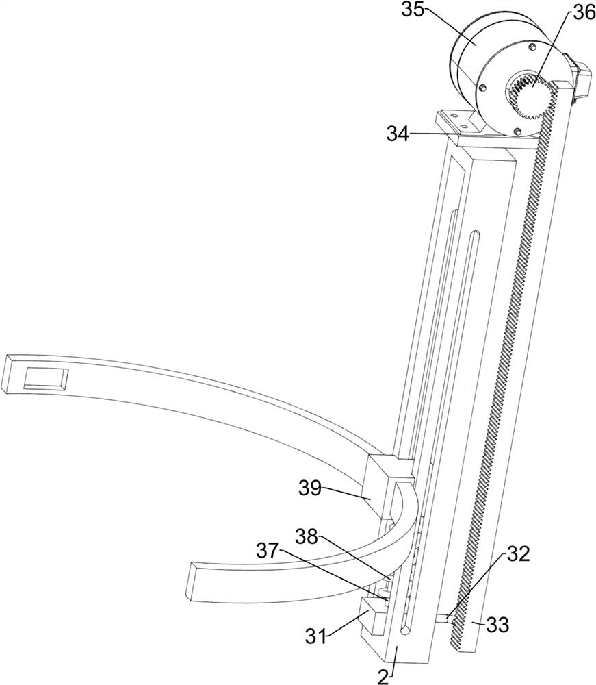
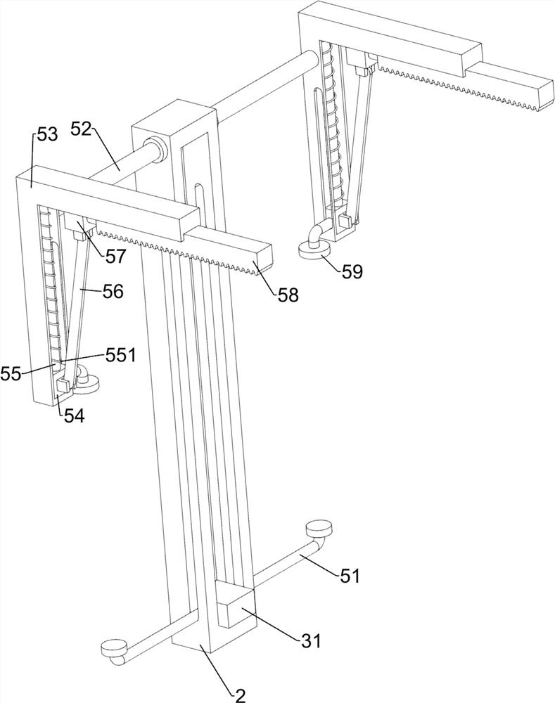
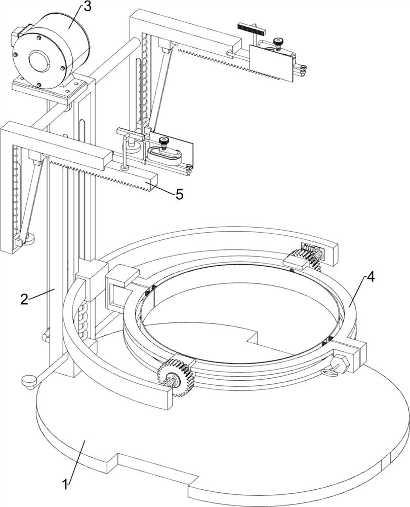
[0022] A chemical tank dumping device, such as Figure 1-6 As shown, it includes a base plate 1, a support frame 2, a lifting mechanism 3, a fixing mechanism 4 and a rotating mechanism 5. The base plate 1 is provided with a support frame 2, and the support frame 2 is provided with a lifting mechanism 3 that lifts and lowers by rotating. The lifting mechanism 3 is provided with a fixing mechanism 4 which is fixed by rotation, and the support frame 2 is provided with a rotation mechanism 5 which is rotated by sliding.

[0023] When using this device to unload chemical barrels, the staff will fix the chemical barrels that need to be unloaded through the fixing mechanism 4. After the fixing is completed, the lifting mechanism 3 will drive the chemical barrels to rise. When the chemical barrels rise to a certain height, The staff drives the chemical barrel to rotate through the rotating mechanism 5, so as to discharge the material. After the completion, the staff controls the rotat...

Embodiment 2

[0031] On the basis of Example 1, such as figure 1 and image 3 As shown, a handle 6 is also included, and the front side of the bolt 491 is welded with the handle 6 .

[0032] When fixing the chemical barrel, the staff turns the handle 6 to drive the bolt 491 to rotate, thereby moving the clamping block 44 outward through the nut 49, then puts the chemical barrel between the two clamping blocks 44, and then turns the handle 6 to drive the bolt 491 reversal fixes the chemical barrel, so it is more convenient for people to use by twisting the handle 6.

[0033] On the basis of Example 1, such as figure 1 and Figure 5 As shown, it also includes a second connecting frame 7, a third rack 8, a third connecting frame 9, a special-shaped block 10, a fourth connecting frame 11, a third gear 12, a rotating rod 13, a second torsion spring 14, a second Five springs 15 and push plate 16, the second rack 58 is welded with the second connecting frame 7, the top of the second connecting...


PUM


Abstract

The invention relates to a pouring device, in particular to a chemical barrel pouring device. The technical problem to be solved by the invention is to provide the chemical barrel pouring device whichis time-saving and labor-saving, does not cause harm to people, can pour out medicines or dyes adhered to the inner wall of a chemical barrel, does not cause waste and is high in safety. The chemicalbarrel pouring device comprises a bottom plate, a support frame which is arranged on the bottom plate, a lifting mechanism which is arranged on the support frame and used for lifting in a rotating mode, a fixing mechanism which is arranged on the lifting mechanism and used for fixing in a rotating mode, and a rotary mechanism which is arranged on the support frame and used for rotating in a sliding mode. When the chemical barrel is poured through the lifting mechanism, the chemical barrel can be driven to ascend and descend, and people can pour materials more conveniently; the chemical barrelneeding to be poured can be fixed through the fixing mechanism, so that people can pour the materials more conveniently; and the chemical barrel can be rotated to pour the materials through the rotary mechanism.

Description

technical field [0001] The invention relates to an unloading device, in particular to an unloading device for chemical barrels. Background technique [0002] Chemical barrels are tools used in chemicals, dyes, and pesticides. When emptying chemical barrels, it is generally done manually. [0003] At present, when chemical tanks are unloaded, the chemical tanks are generally opened manually, the chemical tanks are tilted, and then unloaded. When unloading, people need to hold the chemical tanks all the time. In this way, it takes a lot of time Manpower, this method is easy to get the medicine or dye in the chemical barrel on the body when pouring the material, thus causing harm to people. The dye is poured out, thereby causing waste and inconvenient for people to use. [0004] Therefore, it is necessary to develop a chemical barrel dumping device that saves time and effort, does not cause harm to people, can pour out the medicine or dyestuff stuck on the inner wall of the ...

Claims


Application Information

Patent Timeline
Patent Type & Authority Applications(China)
IPC IPC(8): B65G65/23B65G69/08B67C9/00
CPCB65G65/23B65G69/08B67C9/00
Inventor 朱嘉亨
Owner 辛集市九元化工有限责任公司
Why Eureka
Try Eureka