Crawler crane boom structure and crawler crane

A crawler crane and jib technology, applied in the field of crawler crane jib structure, can solve the problems of increased working cost, high use cost and high use cost, achieve precise control of working range, precise control of hoisting load, and reduce use cost. Effect

Inactive Publication Date: 2015-09-16
XCMG CONSTR MACHINERY
View PDF3 Cites 2 Cited by
  • Summary
  • Abstract
  • Description
  • Claims
  • Application Information

AI Technical Summary

Problems solved by technology

[0008] 1. Working condition of single-bracket fixed jib Since the included angle between the main jib and the fixed jib is fixed, only by changing the elevation angle of the main jib to achieve different working heights and working radii, the degree of increase in the working range is very limited
[0009] 2. The double-bracket tower jib can double the amplitude of the main arm and the tower jib, which has a relatively wider operating range. However, due to the characteristics of the tower jib, it is necessary to have a strong enough main arm to support the tower. The jib has a strong enough main engine to maintain the stability of the whole vehicle. Therefore, if a crawler crane with a small tonnage below 100 tons needs to be equipped with a tower jib, the cost increase accounts for a large proportion of the cost of the whole vehicle, and the use cost is high. It is not recommended to increase
[0010] 3. For medium and large tonnage crawler cranes, if a tower jib is required, double brackets, tower jibs, front and rear pull plates, and luffing wire rope systems need to be added. The relatively high cost of use and relatively complicated construction operations
[0011] 4. For the use of small tonnage crawler cranes, when it is difficult to increase the working conditions of the tower jib, and at the same time it is proposed to meet the higher and wider operating range, the user can only switch to a larger tonnage crawler crane or Changing to a truck crane with a larger tonnage, etc., will greatly increase the cost of use and reduce the utilization rate of resources

Method used


Image

  • Crawler crane boom structure and crawler crane
  • Crawler crane boom structure and crawler crane
  • Crawler crane boom structure and crawler crane

Examples


Embodiment Construction

[0040] The present invention will be further described below in conjunction with the accompanying drawings.

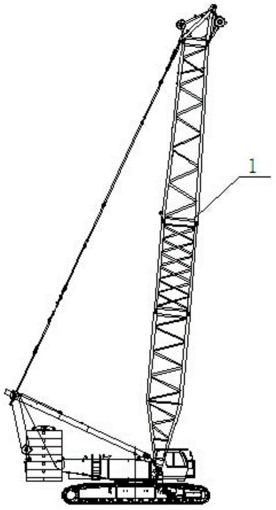
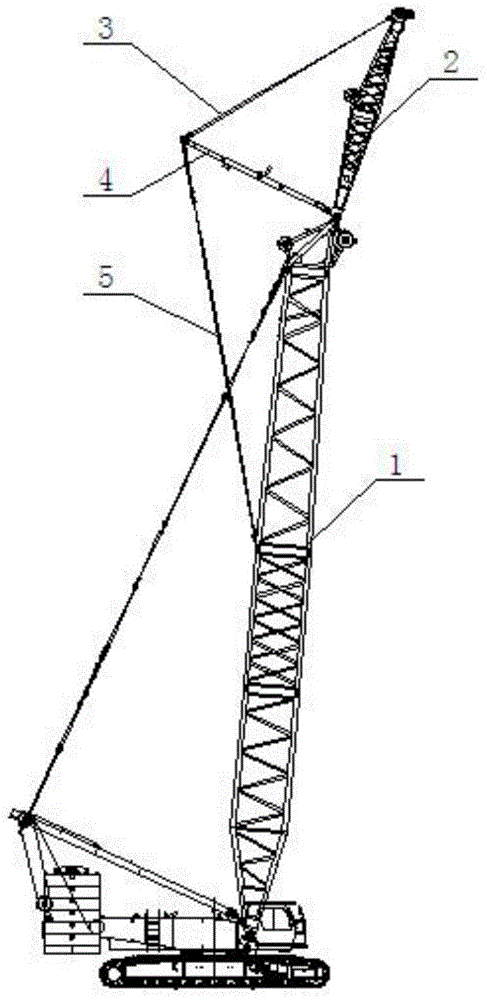
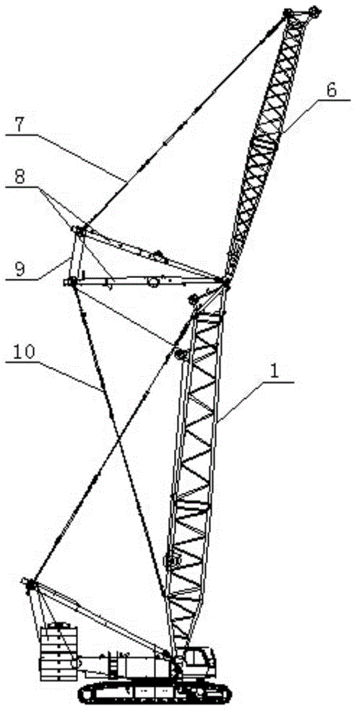
[0041] like Figure 4 to Figure 9 As shown, the boom structure of the crawler crane includes a fixed jib front pull plate 3 connecting the main arm 1 and the fixed jib 2, a single bracket 4 and a fixed jib rear pull plate 5;

[0042] The front pull plate 3 of the fixed jib and / or the rear pull plate 5 of the fixed jib are connected to the single bracket 4 through a luffing pulley block 11;

[0043] A guide pulley 12 and a luffing winch mechanism 13 are installed on the main arm 1;

[0044] The luffing hoisting mechanism 13 is connected to the guide pulley 12 and the luffing pulley block 11 through a wire rope.

[0045] Through the structure of the single bracket 4 and the correspondingly added luffing pulley block 11, the structural forms of the single bracket fixed jib and the double bracket tower jib in the prior art are replaced, and it is the front and rear of th...


PUM


Abstract

The invention discloses a crawler crane boom structure and a crawler crane, and belongs to the crawler crane boom structure technology field. The crawler crane boom structure comprises a fixed auxiliary boom front pulling plate (3) connecting a main boom (1) with a fixed auxiliary boom (2), a single support (4) and a fixed auxiliary boom rear pulling plate (5). The fixed auxiliary boom front pulling plate (3) and / or the fixed auxiliary boom rear pulling plate (5) are connected with the single support (4) through an amplitude variation pulley block (11). A guiding pulley (12) is installed on the main boom (1) and an amplitude variation hoisting mechanism (13). The amplitude variation hoisting mechanism (13) is connected with the guiding pulley (12) and the amplitude variation pulley block (11) through a wire rope. The crawler crane boom structure can widen a working scope of an original single support fixed auxiliary boom and can achieve functions of a double-support tower-type auxiliary arm, the requirement of small-tonnage products for boom addition is met, the usage cost is lowered, a movable-type tower crane working mode can be evolved, and multiple functions of one machine are achieved.

Description

technical field [0001] The invention relates to a crawler crane, in particular to a crawler crane boom structure and a crawler crane including the boom structure, belonging to the technical field of crawler crane boom structures. Background technique [0002] Crawler cranes are widely used in electric power construction, metallurgical construction, chemical construction, bridge construction, water conservancy construction and other occasions due to their characteristics such as heavy lifting, good ground adaptability, 360° all-round operation, and multiple combinations of booms. [0003] Modern hoisting puts forward higher requirements for lifting equipment. With the same tonnage and the same configuration, cranes are required to have a larger working range, higher lifting height, and wider operating range. How to solve the problem in the case of limited resources? It is the future development direction of crawler cranes to exert greater potential under the environment. [...

Claims


Application Information

Patent Timeline
IPC IPC(8): B66C23/64B66C23/36
CPCB66C23/64B66C23/36B66C2700/03
Inventor 崔丹丹孙起贵余钦伟李聪
Owner XCMG CONSTR MACHINERY
Why Eureka
Try Eureka