Deodorizing floor drain

A floor drain and deodorization technology, applied in waterway systems, drainage structures, water supply devices, etc., can solve the problems of small water output, slow water output, and untimely water output, and achieve effective contact, safe and reliable sealing, and prevent odor from overflowing. Effect

Active Publication Date: 2015-09-16
TAIZHOU HAITIAN BRASS MFR
View PDF8 Cites 4 Cited by
  • Summary
  • Abstract
  • Description
  • Claims
  • Application Information

AI Technical Summary

Problems solved by technology

But the floor drain of existing structure can not prevent the overflow of foul smell automatically, and it mainly has the following disadvantages: 1, the water storage time in the groove is too long and easy to breed bacteria; 2, if the stored water evaporates, bad smell is very easy to enter the room; 3 , When the sewer is blocked, the floor drain cannot prevent sewage from entering the room through the sewer
However, a sealing ring is fixed on the inner side wall of the inner cylinder, and the sealing ring has a certain thickness, which leads to a further reduction in the size of the entire water outlet, and the water output per unit time of the entire floor drain is small, which may cause slow water discharge and insufficient water discharge. timely phenomenon occurs
Moreover, the contact area between the sealing ring and the sealing plate is small, once the position of the sealing cover is shifted a little, it will easily lead to sealing failure, which will affect the sealing and deodorant performance

Method used


Image

  • Deodorizing floor drain
  • Deodorizing floor drain
  • Deodorizing floor drain

Examples


Embodiment 1

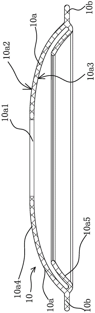
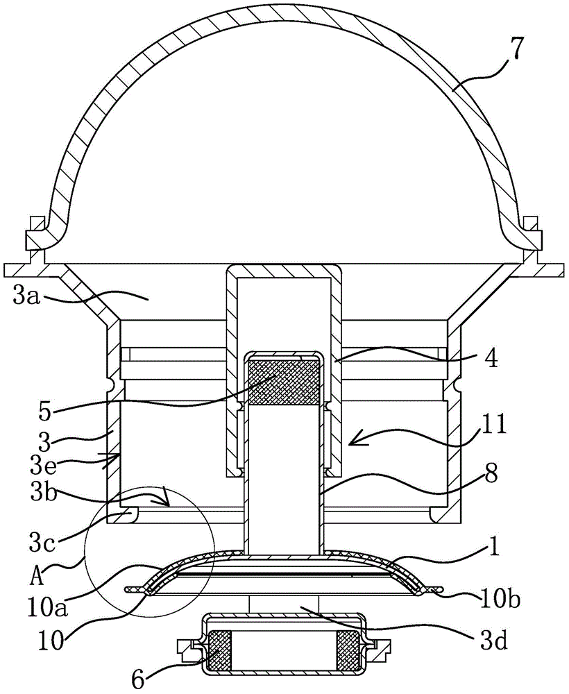
[0043] like Figure 1 to Figure 5 As shown (the following content is only for the convenience of illustrating the floor drain in the illustration, and it is actually not the only structure), the floor drain includes an outer cylinder 9, an inner cylinder 3 with a water inlet 3a and a water outlet 3b, a panel 2, and a panel 2 is located above the inner cylinder 3 and the water inlet 3a communicates with the panel 2 (outer cylinder 9 and panel 2 can refer to Figure 7 ), the panel 2 in this case can be integrally formed with the inner cylinder 3 or can be designed to be detachably connected, which can be determined according to the actual situation. A guide mechanism 11 is fixed inside the inner cylinder 3 to allow the sealing plate 1 to slide up and down in the vertical direction. 6 is located below the sealing plate 1, so that the sealing plate 1 is connected with a permanent magnet one 5 and the permanent magnet one 5 is located at the top of the sealing plate 1, and the fir...

Embodiment 2

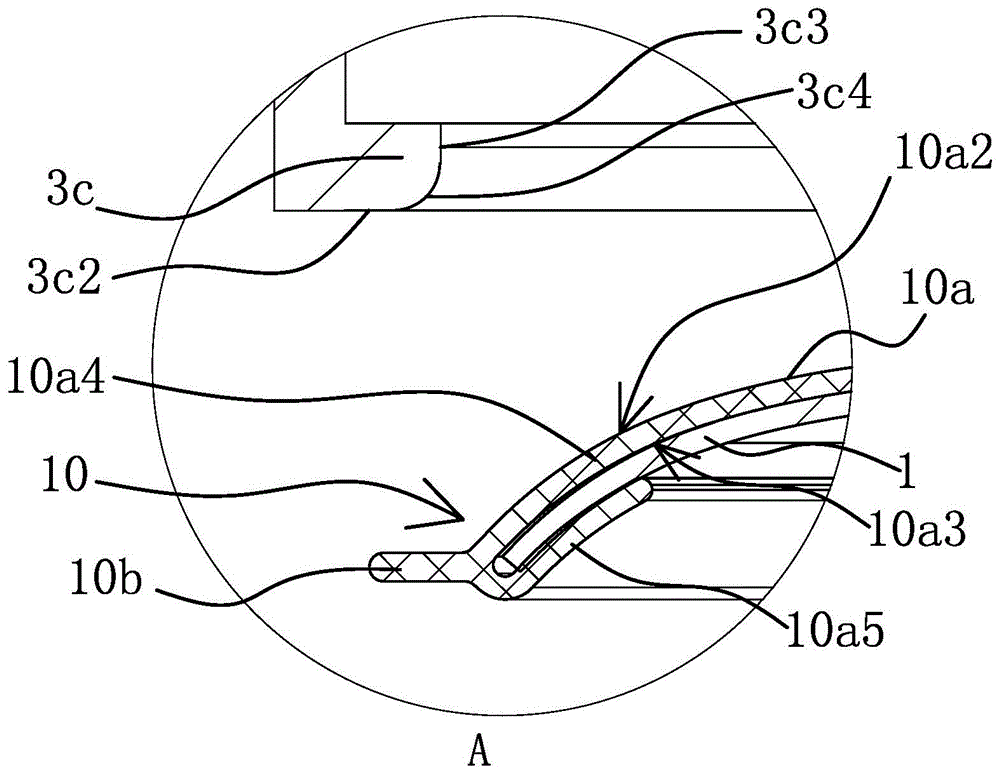
[0054] like Figure 6 to Figure 8 As shown, the structure and principle of this embodiment are basically the same as those of Embodiment 1, the difference lies in: the central hole 10a1 in this embodiment also has an extension part 10c and a gathering part 10d extending upward from the main body 10a, for example, like Image 6 As shown, the extension part 10c and the gathering part 10d also cover the permanent magnet-5, and the entire sealing member 10 can not only play an elastic sealing role, but also effectively isolate the permanent magnet-5 from sewage and dirt. Therefore, its service life is ensured and the water outlet 3b is prevented from being blocked, and the permanent magnet-5 can also be prevented from being corroded by sewage. In addition, the cross-section of the annular retaining edge 3c in this embodiment is stepped, including two annular steps 3c1, which can more effectively perform segmental sealing. And what is shown in the figure is a schematic diagram of...

Embodiment 3

[0056] The structure and principle of this embodiment are basically the same as that of Embodiment 1, the difference is that: the water outlet of the inner cylinder 3 is not provided with an annular retaining edge 3c, but is directly installed at the lower port of the inner cylinder 3 There is an arc surface 3c4 matched with the sealing part 10 to realize the effect of increasing the sealing area. And the caliber of the water outlet 3b in this solution will be correspondingly much larger, which can ensure that more sewage is discharged per unit time and prevent clogging, so as to ensure smooth water outlet.


PUM


Abstract

The invention provides a deodorizing floor drain, and belongs to the technical field of buildings. The problems that an existing floor drain is unsmooth in water drainage, and seal ineffectiveness is not likely to occur are solved. The deodorizing floor drain of the improved structure comprises an outer cylinder, an inner cylinder and a panel, wherein the inner cylinder is provided with a water inlet and a water outlet, the panel is located above the inner cylinder, and a seal plate is arranged inside the inner cylinder. The deodorizing floor drain is characterized in that the seal plate is in a dish shape and is located at the water outlet, the edge of the seal plate is wrapped with a seal part, the seal part comprises a round body and a seal portion, the section of the round body is in a U shape, the seal part extends outwards from the body, and the seal portion of the seal part abuts against the water outlet in the inner cylinder. The deodorizing floor drain of the improved structure is smooth in water drainage and stable in sealing.

Description

technical field [0001] The invention belongs to the technical field of construction, and relates to a floor drain, in particular to a deodorant floor drain. Background technique [0002] With the improvement of people's quality of life, the demand for home decoration materials is also increasing. Floor drains are one of the most common decoration accessories, which are installed on the ground surfaces of kitchens, bathrooms and balconies. Although the floor drain is small, it involves thousands of households and is related to people's health and environmental sanitation. The traditional floor drain is equipped with a movable panel on the shell, with drainage holes on the panel, and the hemispherical metal cover is buckled in the groove. By storing water in the groove, it prevents the odor of the sewer from overflowing and the pests in the sewer from entering the room. But the floor drain of existing structure can not prevent the overflow of foul smell automatically, and it ...

Claims


Application Information

Patent Timeline
Patent Type & Authority Applications(China)
IPC IPC(8): E03F5/04
Inventor 包启全
Owner TAIZHOU HAITIAN BRASS MFR
Why Eureka
Try Eureka