

Connecting structure and connecting method
A technology for connecting structures and connecting parts, which is applied in the fields of construction and civil engineering, and can solve the problems of difficult operation, low efficiency and long working hours.
- Summary
- Abstract
- Description
- Claims
- Application Information
AI Technical Summary
Problems solved by technology
Method used
Image

Examples
Embodiment 1
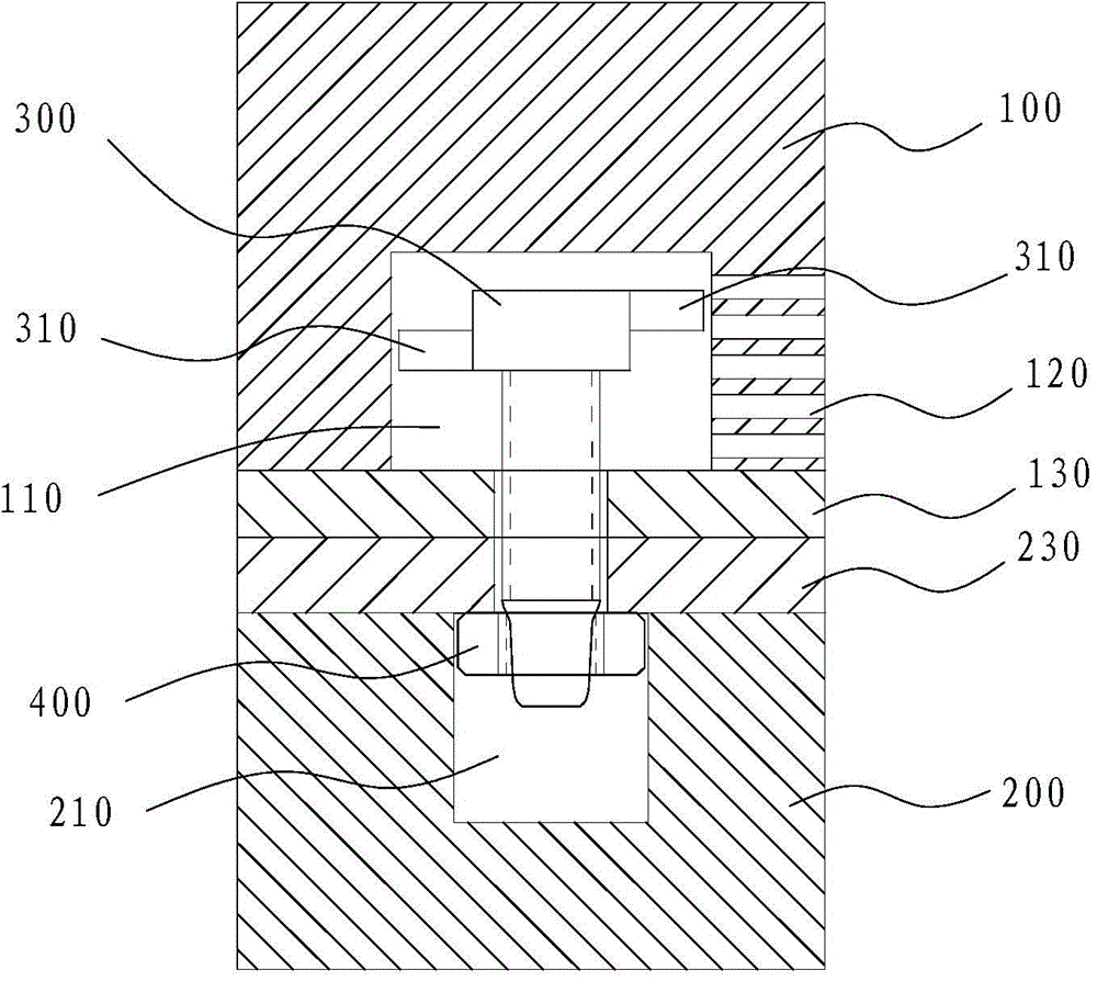
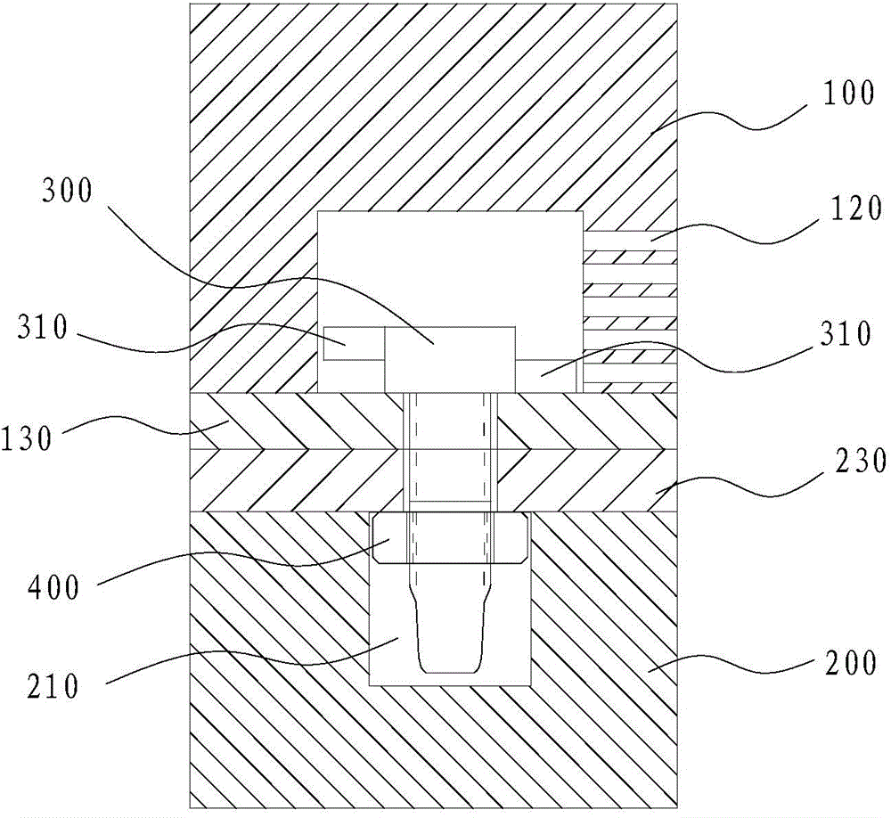
[0055] Such as Figures 1 to 4 As shown, the connecting structure includes a first body, a connecting piece 300 and a second body.
[0056] The first main body includes a first prefabricated part 100 and a first end plate 130, the first prefabricated part 100 is provided with a pre-embedded chamber 110, the pre-embedded chamber 110 is provided with an opening, and the first end plate 130 covers the opening of the pre-embedded chamber 110 , the first end plate 130 is provided with a mounting hole 131 . The installation hole 131 communicates the pre-embedded chamber 110 with the outside. The side wall of the first prefabricated part 100 is also provided with a toggle hole 120, the toggle hole 120 is staggered with the first axis, the toggle hole 120 communicates the pre-embedded chamber 110 with the outside of the first prefabricated part 100, and the toggle hole 120 is used for Insert toggle lever 500. The toggling holes 120 are multi-layered, each layer has a toggling hole ...
Embodiment 2
[0084] The difference between embodiment two and embodiment one is:
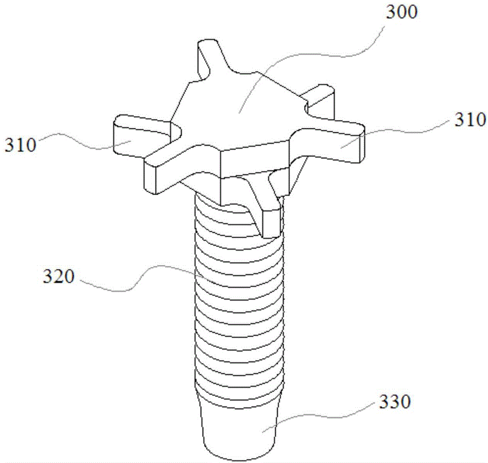
[0085] Such as Figures 9 to 10 As shown, there is only one layer of toggle parts 310 in the connector 300, and there are three toggle parts 310 evenly distributed in the circumferential direction.
[0086] The toggling holes 120 are multi-layered, and each layer of toggling holes 120 is two opposite and staggered.
[0087] When tightening the connection, first use the toggle hole 120 of the same layer to operate, and when the first toggle part 310 turns over a certain angle, the first toggle part 310 exceeds the "effective" position of the first toggle hole 120. Working range", because there are two toggle holes 120, at this time the second toggle part 310 just enters the "effective working range" of the second toggle hole 120, and the toggle lever 500 is moved from the first toggle hole 120 is drawn out, inserted into the second toggle hole 120, and continues to toggle the toggle part 310 to make it rota...
Embodiment 3
[0089] The difference between embodiment three and embodiment one is:
[0090] The connector also includes a sleeve, the sleeve is provided with a sleeve hole, and the toggle part is connected to the outer wall of the sleeve; the first end of the screw rod is installed in the sleeve hole. During installation or disassembly, the first threaded part 310 is tightened or unscrewed, and the first threaded part 310 translates axially in the sleeve hole, but the sleeve 340 does not translate relative to the first preform 100, which can reduce the number of toggle holes The quantity and distribution range of 120 affect the shape of the first preform 100 as little as possible, so as to ensure the strength of the first preform 100 . In this embodiment, two layers of toggle parts 310 are provided, and each layer has three toggle parts 310. Only two layers of toggle holes 120 arranged in a row and each layer of toggle holes 120 are provided to complete the process. Install operation.
PUM
 Abstract
Description
Claims
Application Information