Double clutch structure reducer

A dual-clutch, reducer technology, applied in clutches, mechanical drive clutches, clutches that mesh with each other, etc., can solve problems such as complex structures, achieve the effect of small volume, simple clutch structure, and guaranteed transmission ratio

Active Publication Date: 2017-09-05
SKYBEST ELECTRIC APPLIANCE SUZHOU CO LTD
View PDF5 Cites 0 Cited by
  • Summary
  • Abstract
  • Description
  • Claims
  • Application Information

AI Technical Summary

Problems solved by technology

The disadvantage of this technical solution is that the friction clutch mechanism 7 needs the axial movement of the shrapnel 10 to realize the combination and separation, and its structure is complicated, and the friction clutch mechanism 7 is arranged outside the worm wheel. When the friction clutch mechanism 7 is combined and separated, the worm wheel also needs axial move

Method used


Image

  • Double clutch structure reducer
  • Double clutch structure reducer
  • Double clutch structure reducer

Examples


Embodiment Construction

[0041] The present invention will be described in further detail below in conjunction with the accompanying drawings.

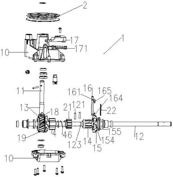
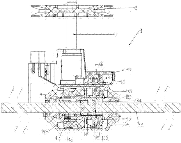
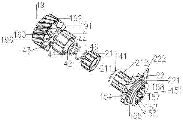
[0042] refer to figure 1 with figure 2 , the reducer 1 can work between the source power input shaft 11 and the power output shaft 12, which is usually used in self-propelled mechanical equipment. For example, in a self-propelled lawn mower, the power is transmitted to the pulley 2 installed on the input shaft through a transmission belt (not shown in the figure), and the power is output by the power output shaft 12 through the speed reducer. Conventionally, the drive wheels of the self-propelled machine are driven by the power take-off shaft 12 . In order to be suitable for walking, the rotational speed of the output shaft 12 is smaller than that of the input shaft in the application of self-propelled mechanical equipment, and its torque is greater than that of the input shaft 11 .

[0043] The reducer has a housing 10, and the housing is connected toget...


PUM


Abstract

The invention relates to a double-clutch structure reducer, which has a source power input shaft and a power output shaft; a first clutch device and a second clutch device; the first clutch device and the second clutch device can be axially separated and combined Position movement; the first clutch device is always combined earlier than the second clutch device, and is always separated than the second clutch device; the first clutch device is axially arranged between the driven device and the second clutch device ; The first clutch device and the second clutch device are coaxial and rotate synchronously; the clutch control device operates the second clutch device to move axially from the disengaged position to the combined position, the first clutch device is driven by the second clutch device shaft The speed reducer of the present invention has the advantages of smaller volume, simpler structure, stable operation and guaranteed transmission ratio.

Description

technical field [0001] The invention relates to a speed reducer, which uses a self-propelled machine and adopts a double-clutch structure to realize the smooth transmission of the speed reducer, reduce the impact force of the transmission parts of the speed reducer, and reduce the vibration of the whole machine during the clutch process of the speed reducer. Background technique [0002] Reducers are mainly used in self-propelled machinery, such as propelling lawn mowers. Traditional reducers use friction rings or friction discs for transmission. For example, the US patent publication No. US2003006074 discloses a reducer, which includes a drive. A driving friction ring is installed on the top, and a follower is also included, and a driven friction ring is arranged on the follower. The power of the driving part comes from the pulley connected with the transmission belt. When the clutch is combined, the driven friction ring moves axially to the position where it combines with ...

Claims


Application Information

Patent Timeline
Patent Type & Authority Patents(China)
IPC IPC(8): F16H3/08F16H57/028
CPCF16H3/08F16H57/023A01D69/08F16D11/10F16D11/14F16D23/02F16D2500/1102A01D2101/00F16D21/00F16D23/12F16D2023/126
Inventor 安红磊雷艳清张天才
Owner SKYBEST ELECTRIC APPLIANCE SUZHOU CO LTD
Why Eureka
Try Eureka