Air capacity control method of air purifying device and air purifying device

An air purification equipment and air volume control technology, which is applied in space heating and ventilation control input, heating and ventilation control system, control input related to air characteristics, etc., can solve user misleading, unscientific, and the system does not issue replacement prompts, etc. question

Inactive Publication Date: 2015-09-16
杨志荣 +1
View PDF7 Cites 39 Cited by
  • Summary
  • Abstract
  • Description
  • Claims
  • Application Information

AI Technical Summary

Problems solved by technology

It is obviously inaccurate and unscientific to define the service life of the filter element by using the timing prompt method and ignoring the use environment to define the service life of the filter element.
This metho...

Method used


Image

  • Air capacity control method of air purifying device and air purifying device
  • Air capacity control method of air purifying device and air purifying device
  • Air capacity control method of air purifying device and air purifying device

Examples


Embodiment 1

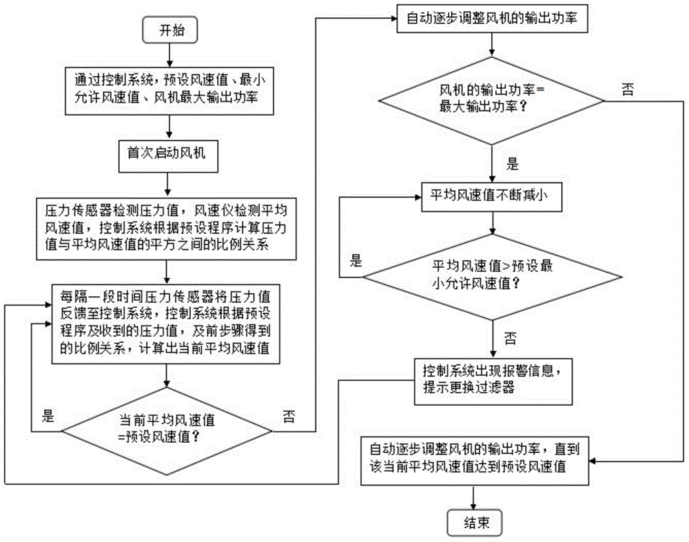
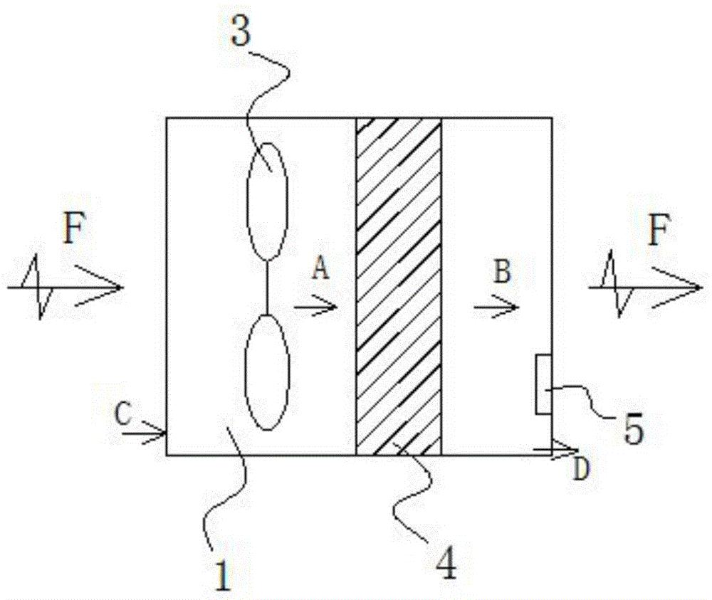
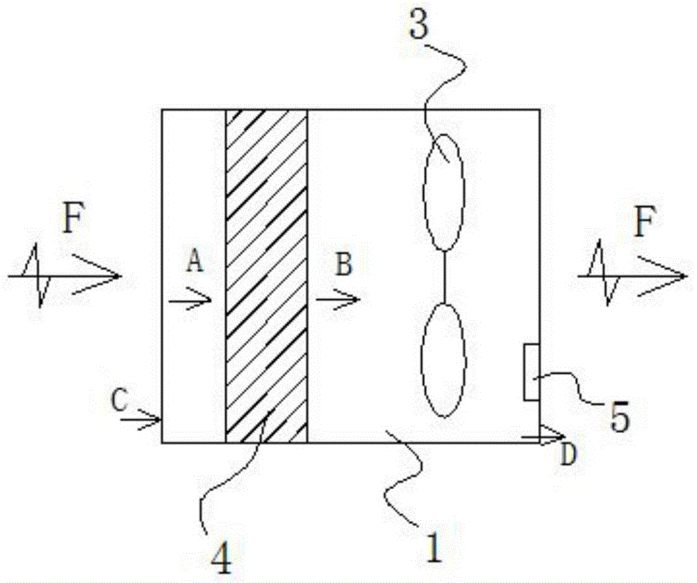
[0052] Please refer to figure 2 and image 3, Embodiment 1 of the present invention discloses an air purification device capable of air volume control, which includes a control system and a body 1, the body 1 has an air inlet C and an air outlet D, and a fan 3 and a filter are arranged inside the body 1. device 4, such as figure 2 As shown, the fan 3 is arranged on the position of the upwind direction A of the filter 4, or, as image 3 The blower 3 shown is arranged at a position in the downwind direction B of the filter 4 . A pressure sensor 5 is provided at any position in the downwind direction B of the filter 4 . The pressure sensor 5 is arranged inside the body 1 and at any position in the downwind direction B of the filter 4 . exist figure 2 and image 3 Among them, F is the ventilation direction of the air purification equipment of the present invention. Meanwhile, the control system has a preset program for analyzing and processing the pressure data of the se...

Embodiment 2

[0055] Please refer to Figure 4 , Figure 5 The main difference between the second embodiment and the first embodiment is that a ventilation duct 2 is connected to the air outlet D of the body 1, and the pressure sensor 5 is arranged inside the body 1 and is located at any position in the downwind direction B of the filter 4. position, such as Figure 4 shown; at the same time, the pressure sensor 5 can also be arranged at any position on the ventilation duct 2, such as Figure 5 shown. Other structures are the same as those in the embodiment, and will not be repeated here.

[0056] In this embodiment, the pressure sensor 5 is arranged at any position on the ventilation duct 2, as long as the pressure sensor 5 is located in the downwind direction B of the filter 4, the function of the first embodiment can be realized.

Embodiment 3

[0058] The main difference between Embodiment 3 and Embodiment 1 is that: Figure 6 As shown, a filter layer 6 is also provided at the air inlet C of the body 1, and the filter layer 6 is a dust filter. Other structures are the same as those in the embodiment, and will not be repeated here.

[0059] In this embodiment, preferably, the dust removal filter is a stainless steel dust removal filter. The air containing organic compounds passes through the stainless steel dust filter to remove dust, so that the air can be preliminarily purified before entering the body. This enables the pressure sensor 5 to better detect the pressure at its location to control the air volume output, and at the same time monitor the life of the filter element.


PUM


Abstract

The invention discloses an air capacity control method of an air purifying device. The air capacity control method includes the following steps: 1, the air purifying device is arranged, and a pressure sensor is arranged at the leeward position of a filter; 2, an air speed value is preset; 3, the pressure sensor detects pressure values, an anemoscope detects average air speed values, and a control system calculates scale values between the pressure values and squares of the average air speed values according to a preset program; 4, the pressure sensor feeds the pressure values back to the control system at set intervals, and the control system calculates current average air speed values according to the preset program, the received pressure values and the scale values in the previous step; 5, if the current average air speed values are smaller than the preset air speed value, the output power of a draught fan is automatically and gradually adjusted till the current average air speed values reach the preset air speed value, and therefore the air capacity is controlled to be stably output. The invention further discloses the air purifying device. The air capacity control method and the air purifying device have the functions of high-accuracy air capacity control and accurate filter-replacement reminding.

Description

technical field [0001] The invention relates to air purification equipment, in particular to an air volume control method and equipment for air purification equipment. Background technique [0002] The air volume adjustment method adopted by conventional air purification equipment is mainly to adjust the output power of the fan through preset gear speeds to adjust the air volume output in stages. Its shortcomings are mainly manifested in the following three aspects: 1) For ventilation and purification systems that have strict requirements on air volume output control, the air volume control accuracy and adaptability are poor (the system cannot detect wind speed changes in real time); 2) because its working principle is The air volume is output according to the pre-set power gear. As the equipment running time increases, the resistance coefficient of the built-in filter of the purification equipment will also increase. When the output power is constant, the air volume The ou...

Claims


Application Information

Patent Timeline
IPC IPC(8): F24F11/00F24F11/02
CPCF24F11/30F24F11/62F24F11/64F24F11/77F24F11/89F24F2110/00F24F2110/30F24F2110/40Y02B30/70
Inventor 杨志荣杨日强
Owner 杨志荣
Why Eureka
Try Eureka