Heat exchanger and air conditioning unit

A technology of heat exchangers and heat exchange tubes, which is applied in the field of air conditioning, can solve the problems that the efficiency of heat exchangers cannot be fully exerted, affect the comfort of users, and the heat exchange efficiency of heat exchange tubes decreases, so as to eliminate adverse effects and shorten Effects of defrosting time and frosting area reduction

Active Publication Date: 2015-09-16
GREE ELECTRIC APPLIANCES INC
View PDF10 Cites 10 Cited by
  • Summary
  • Abstract
  • Description
  • Claims
  • Application Information

AI Technical Summary

Problems solved by technology

[0003] For a tube-fin heat exchanger with multiple rows of tubes, as the number of heat exchange tubes increases, the heat exchange efficiency of the heat exchange tubes gradually decreases from the windward side to the leeward side, so that the efficiency of the entire heat exchanger cannot be fully utilized.
At the same time, when the air conditioner unit is in heating operation, the tube-fin heat exchanger located outdoors will experience frost. As the operating time increases, the frost layer will gradually spread from the heat exchange tube on the windward side to the heat exchange tube on the leeward side. The heat pipe makes the whole heat exchanger covered with frost layer and thickens continuously, thus affecting the performance of the whole machine
In order to maintain the performance of the unit, the system needs to defrost the entire outdoor heat exchanger, which not only consumes a lot of energy, but also takes a long time to defrost, which seriously affects the comfort of users

Method used


Image

  • Heat exchanger and air conditioning unit
  • Heat exchanger and air conditioning unit
  • Heat exchanger and air conditioning unit

Examples


Embodiment Construction

[0033] In order to make the object, technical solution and advantages of the present invention clearer, the heat exchanger and the air conditioner unit of the present invention will be further described in detail below with reference to the accompanying drawings and embodiments. It should be understood that the specific embodiments described here are only used to explain the present invention, not to limit the present invention.

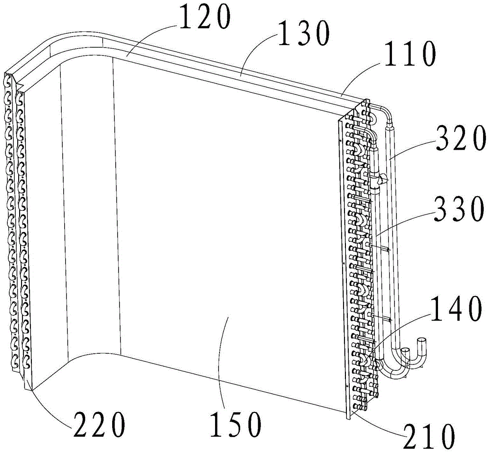
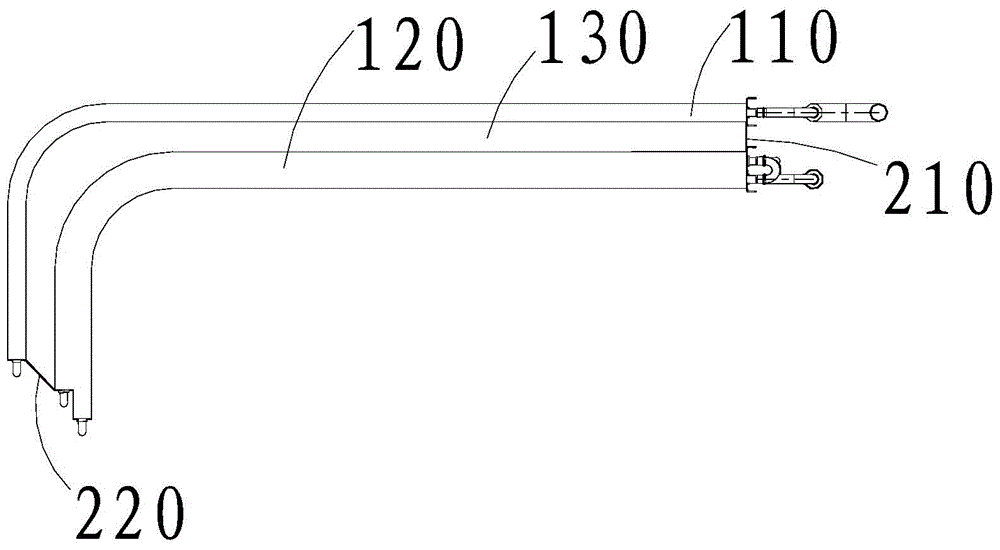
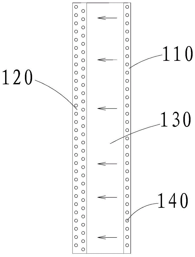
[0034] like Figure 1 to Figure 3 As shown, the present invention provides a heat exchanger, which includes a first heat exchange unit 110 and a second heat exchange unit 120 . Wherein, the first heat exchange unit 110 and the second heat exchange unit 120 are arranged side by side along the air flow direction; meanwhile, a cavity 130 is provided between the first heat exchange unit 110 and the second heat exchange unit 120 . In the present invention, the first heat exchange unit 110 can be arranged on the windward side, and the second heat exchange...


PUM


Abstract

The invention discloses a heat exchanger and an air conditioning unit, wherein the heat exchanger comprises a first heat exchange unit and a second heat exchange unit which are arranged side by side along the flowing direction of the air, and a cavity is arranged between the first heat exchange unit and the second heat exchange unit. According to the heat exchanger and the air conditioning unit, the heat exchange efficiency is effectively improved, the defrosting time is shortened, and the comfort of users during using is improved.

Description

technical field [0001] The invention relates to the technical field of air conditioning, in particular to a tube-fin heat exchanger and an air conditioning unit using the same. Background technique [0002] The heat exchanger is an important part of the air conditioning unit. The tube-fin heat exchanger is a common form of heat exchanger. Due to the different performance and structure of the unit, the tube-fin heat exchangers used are also varied. , there are a row of tubes and multiple rows of tubes and other forms. [0003] For a tube-fin heat exchanger with multiple rows of tubes, as the number of heat exchange tubes increases, the heat exchange efficiency of the heat exchange tubes gradually decreases from the windward side to the leeward side, so that the efficiency of the entire heat exchanger cannot be fully utilized. . At the same time, when the air conditioner unit is in heating operation, the tube-fin heat exchanger located outdoors will experience frost. As the ...

Claims


Application Information

Patent Timeline
Patent Type & Authority Applications(China)
IPC IPC(8): F24F13/30F25B47/00
CPCF24F13/30F25B47/006
Inventor 章秋平张辉黄春李兆东张龙洲
Owner GREE ELECTRIC APPLIANCES INC
Why Eureka
Try Eureka