Heading drift error closed-loop compensation method applied to communication-in-moving inertial navigation system
An inertial navigation system and heading drift technology, which is applied in the field of satellite communication and can solve the problems of satellite tracking accuracy damage of the antenna system in motion and other problems
- Summary
- Abstract
- Description
- Claims
- Application Information
AI Technical Summary
Problems solved by technology
Method used
Image
Examples
Embodiment
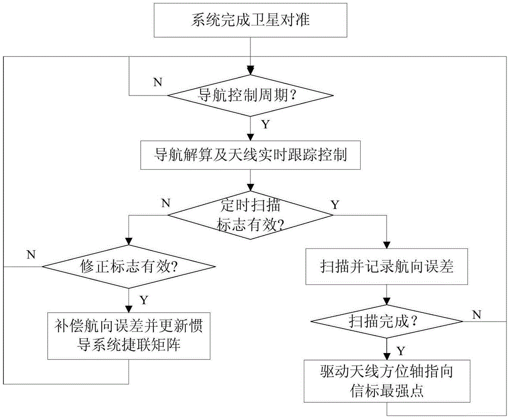
[0056] 1. Set the control navigation period counter M, heading timer SCANFLAG and compensation flag MODIFLAG, the initial value is 0, the preset maximum voltage value XBMAX=4.3V, the step size SAngle=0.01°, the total amount of unilateral scanning ASINGLE=200;
[0057] 2. Control the navigation period counter M and the heading timer SCANFLAG to start counting, when the navigation period counter M counts to 5ms, enter step (3);
[0058] 3. The inertial navigation system calculates the carrier's current pitch angle P=0.5°, roll angle R=0.5°, and heading angle Y=120.0°, then the antenna pitch angle fPitch=49.057437°, polarization angle fJihua=16.596453° and Antenna azimuth angle fYaw=9.373444°;
[0059] 4. Determine the heading timer SCANFLAG≥2min, if it is satisfied, then the antenna azimuth axis angle fYaw=fYaw+SAngle=9.373444°+0.01°=9.38344°, and drive the azimuth axis to rotate, at this time Sum=0.01°, SCnt=1, The real-time voltage value of the beacon read at the same time is...
PUM
 Abstract
Description
Claims
Application Information
 - R&D
- Intellectual Property
- Life Sciences
- Materials
- Tech Scout
- Unparalleled Data Quality
- Higher Quality Content
- 60% Fewer Hallucinations
Browse by: Latest US Patents, China's latest patents, Technical Efficacy Thesaurus, Application Domain, Technology Topic, Popular Technical Reports.
© 2025 PatSnap. All rights reserved.Legal|Privacy policy|Modern Slavery Act Transparency Statement|Sitemap|About US| Contact US: help@patsnap.com


