Detection and positioning method for PLCC component
A positioning method and component technology, applied in image data processing, instruments, calculations, etc., can solve problems such as affecting the positioning accuracy of components, inability to accurately correspond to the index number, poor accuracy and robustness, etc., to improve accuracy and ensure reliability. , the effect of precise positioning
- Summary
- Abstract
- Description
- Claims
- Application Information
AI Technical Summary
Problems solved by technology
Method used
Image
Examples
specific Embodiment approach 1
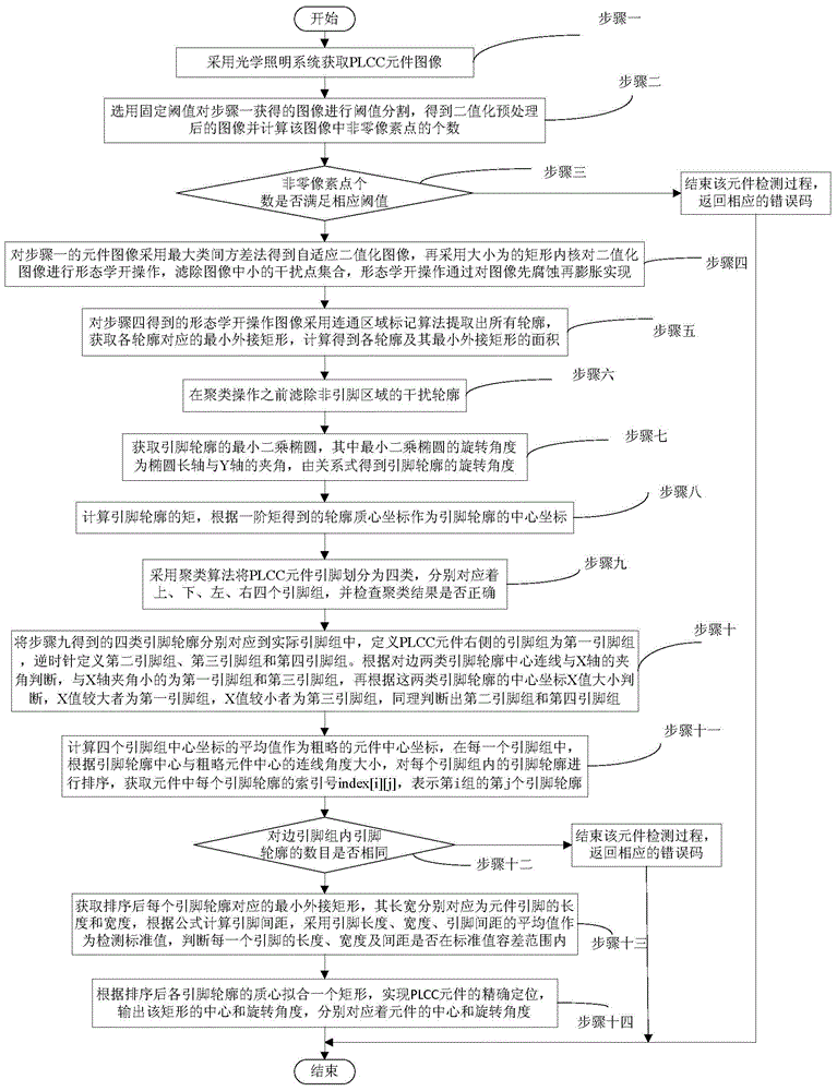
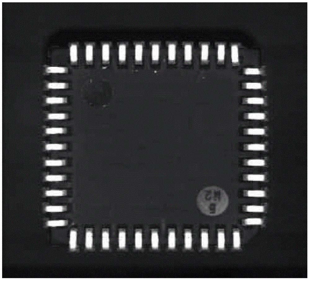
[0035] Specific embodiment one: a kind of detection and positioning method for PLCC element of the present embodiment, realize according to the following steps: Step 1: adopt optical lighting system to obtain PLCC element image;
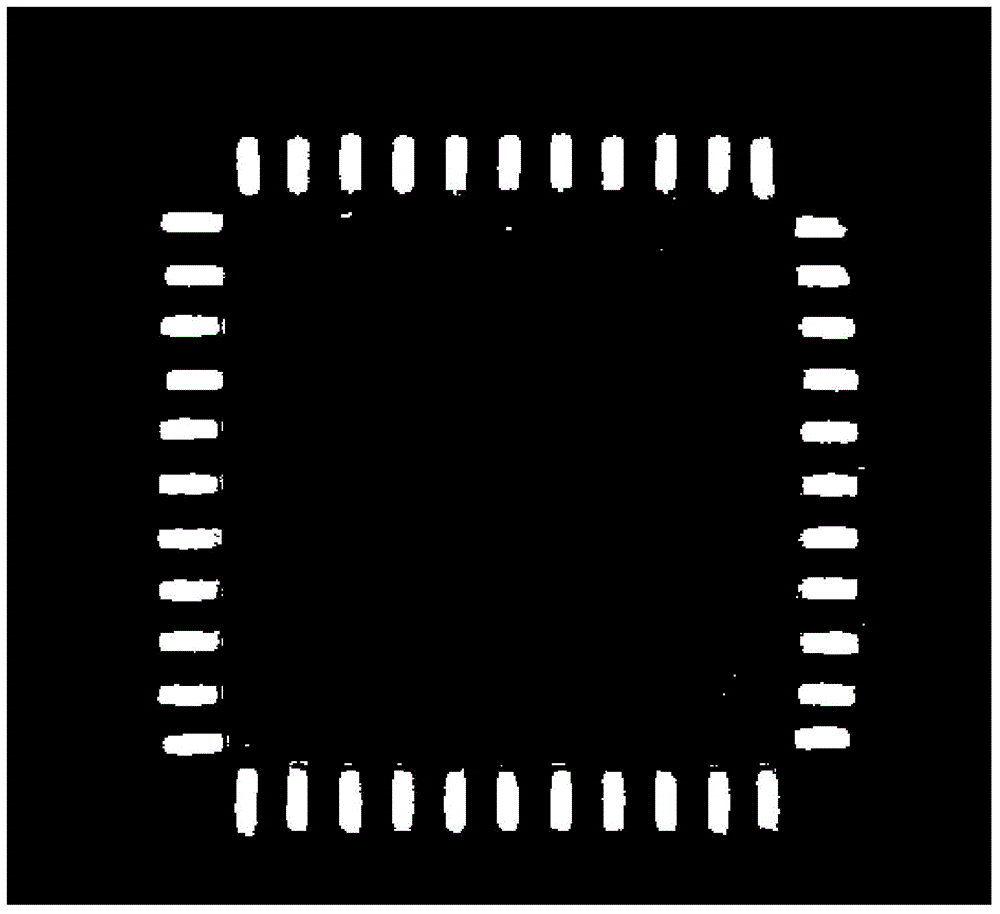
[0036] Step 2: Selecting a fixed threshold to perform threshold segmentation on the PLCC component image obtained in step 1 to obtain a binary preprocessed image and calculate the number of non-zero pixels in the binary preprocessed image;
[0037] Step 3: Determine whether the number of non-zero pixels obtained in step 2 reaches 0.1 to 0.9 times the total number of PLCC component image pixels, if yes, continue to step 4, otherwise end the component detection process and return the corresponding error code;
[0038] Step 4: Use the maximum inter-class variance method on the PLCC component image in step 1 to obtain an adaptive binarized image, and then use a rectangular kernel with a size of 5×5 to perform morphological opening operations on the adapti...
specific Embodiment approach 2
[0053] Step 14: Fit a rectangle according to the centroid of each pin outline after sorting to realize the precise positioning of the PLCC component, output the center and rotation angle of the rectangle, which correspond to the center and rotation angle of the component respectively, and the detection and positioning process ends. Embodiment 2: The difference between this embodiment and Embodiment 1 is that step 6 filters the interference contours in the non-pin area, and the specific process is as follows:
[0054] (1) Perform the first screening according to the rectangularity of the outline: judge whether the ratio of the area of the outline to the area of the smallest circumscribing rectangle is greater than 0.5, if so, keep the outline and the corresponding smallest circumscribing rectangle, otherwise delete;
[0055] (2) Perform the second screening according to the aspect ratio of the smallest circumscribing rectangle: calculate the average value of the aspect ratio...
specific Embodiment approach 3
[0058] Specific implementation mode three: the difference between this implementation mode and specific implementation mode one or two is: the specific steps of step nine are as follows:
[0059] (1) The rotation angle range of the pin profile is [-90°, 90°], where -90° and 90° represent the same rotation direction, and the difference between the rotation angle of the pin profile and the first pin profile rotation angle is used The value is input as the first clustering sample. According to the similar rotation angles of the pin groups on opposite sides, the rotation angles of adjacent pin groups differ by nearly 90°, the pin outlines are divided into two categories, and the average rotation of each category is obtained. Angle and average center coordinates, determine whether the absolute value of the average rotation angle difference between category 1 and category 2 is within [85°, 95°], if so, determine whether the difference between the average center coordinates of categor...
PUM
 Abstract
Description
Claims
Application Information
 - R&D
- Intellectual Property
- Life Sciences
- Materials
- Tech Scout
- Unparalleled Data Quality
- Higher Quality Content
- 60% Fewer Hallucinations
Browse by: Latest US Patents, China's latest patents, Technical Efficacy Thesaurus, Application Domain, Technology Topic, Popular Technical Reports.
© 2025 PatSnap. All rights reserved.Legal|Privacy policy|Modern Slavery Act Transparency Statement|Sitemap|About US| Contact US: help@patsnap.com


