A flameproof device with an interlocking mechanism

An interlocking mechanism and explosion-proof technology, applied to electrical components, electric switches, circuits, etc., can solve problems such as vacuum tube contact adhesion, breakdown, safety production and personal safety hazards, and difficulty in determining modular feed switches. , to achieve the effect of reducing the volume of the space

Active Publication Date: 2017-03-15
侨融电子科技有限公司
View PDF4 Cites 0 Cited by
  • Summary
  • Abstract
  • Description
  • Claims
  • Application Information

AI Technical Summary

Problems solved by technology

However, due to its complex working environment, wet ground, frequent start-up of electrical equipment, etc., or when the circuit breaker in the feed switch is opened, when failures such as vacuum tube contact adhesion and breakdown occur, it is often necessary to maintain or repair it. maintenance, and the currently used feed switch adopts the method of opening the door to cut off the power, or manually opening the gate without opening the door, but it is difficult to determine whether the modular feed switch is completely separated from the main circuit in the flameproof main cavity, so If the staff open the door to cut off the power or the modular feed switch is not completely separated from the main circuit and then open the door for maintenance and troubleshooting, it will bring major safety hazards to the safety of coal mine production and personal safety.
And the old-fashioned flameproof feed switch currently used, manual opening will not be able to achieve the purpose of power-off on the switching power supply side
Because the input side of the circuit breaker in the feeder switch is charged, especially during maintenance and troubleshooting, the load side of the circuit breaker is charged due to the failure of the vacuum tube. If the circuit breaker cannot be completely separated from the main circuit, the safety of the coal mine cannot be guaranteed.

Method used


Image

  • A flameproof device with an interlocking mechanism
  • A flameproof device with an interlocking mechanism
  • A flameproof device with an interlocking mechanism

Examples


Embodiment Construction

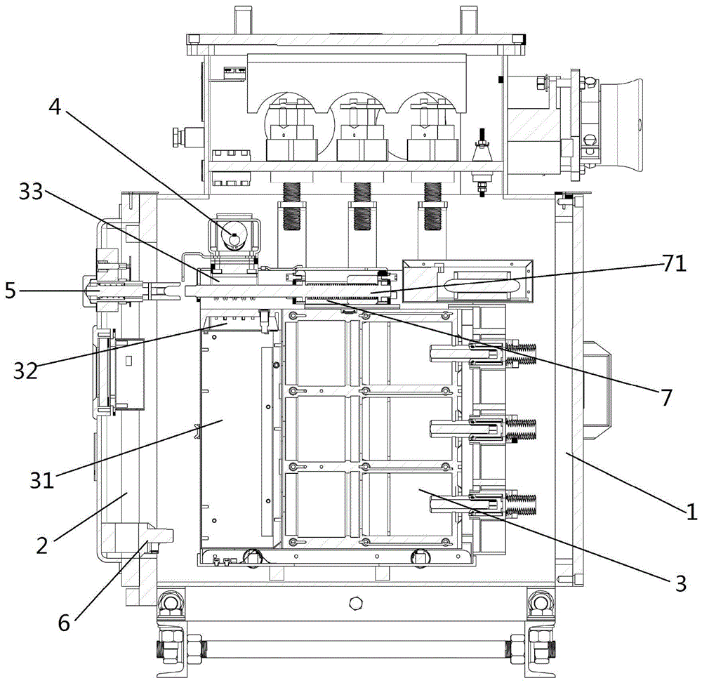
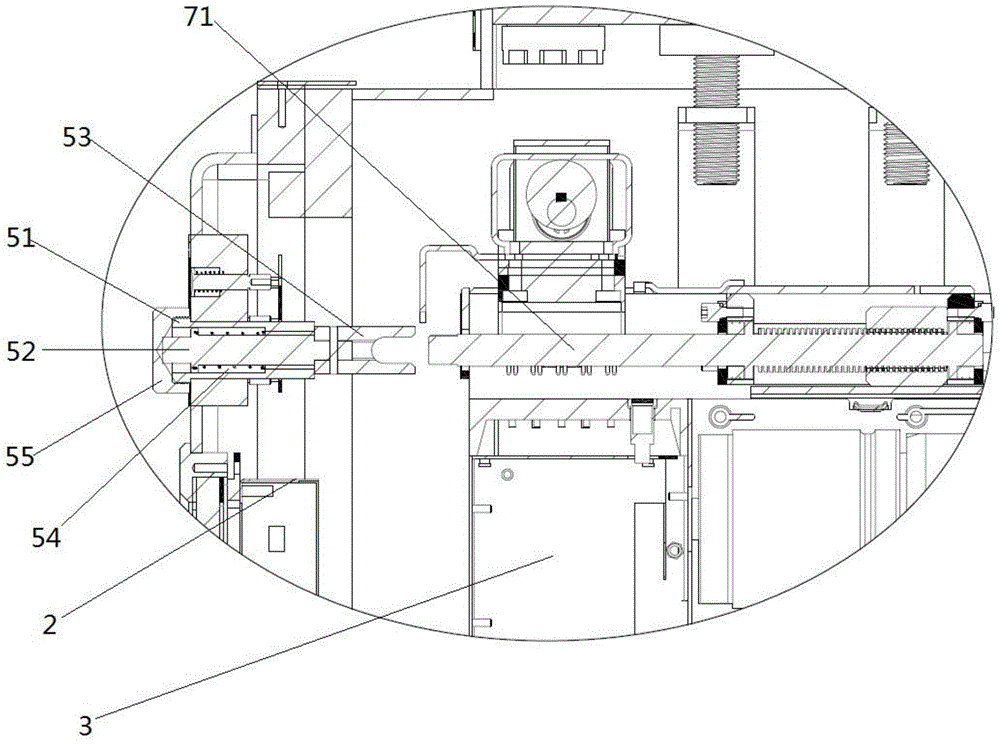
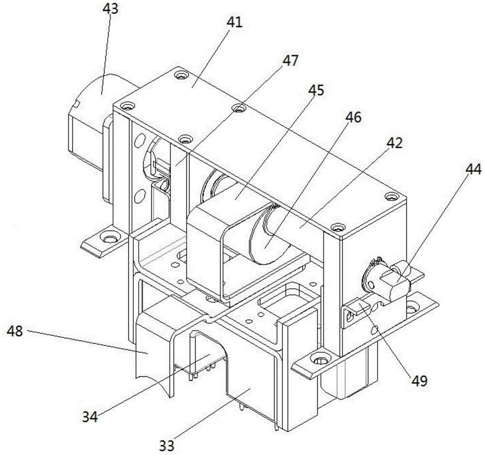
[0030] A flame-proof device with an interlock mechanism comprises a flame-proof casing 1 for placing a modular feed switch 2, a front door 2 arranged on the front side of the flame-proof casing 1, and an interlock mechanism. The interlock mechanism includes a conversion device 4 installed inside the flameproof enclosure 1 for switching on and off the control circuit of the modular feed switch 3, and is installed on the front door 2 for driving the connection between the on and off modular feed switch 3 and the main circuit. The withdrawal mechanism 5 and the locking mechanism 6 used to limit the opening of the front door 2, the conversion device 4 limits the movement of the advancing and withdrawing mechanism 5, and the advancing and withdrawing mechanism 5 limits the movement of the locking mechanism 6.

[0031] The control part 31 of the modular feed switch 3 has a static spring needle seat 32 and a dynamic spring needle seat 33, and the conversion device 4 is arranged above ...


PUM


Abstract

The invention discloses an explosive-proof device having an interlocking mechanism. The device is provided with an explosive-proof shell used for receiving a modular feeder switch and a front door arranged on the front side of the explosive-proof shell. The device has the interlocking mechanism. The interlocking mechanism includes a conversion device arranged in the explosive-proof shell and used for switching on or switching off a control circuit of the modular feeder switch, a push-pull mechanism arranged on the front door and used for controlling the connection of the modular feeder switch and a main circuit, and a locking mechanism used for limiting the opening of the front door. The conversion device limits the movement of the push-pull mechanism. The push-pull mechanism limits the movement of the locking mechanism. Therefore, risks of mine methane and coal dust explosion due to electrical failure caused by insufficient electric gap between a detached circuit breaker in the modular feeder switch and the main circuit and safety guarantee is provided for maintenance workers. Besides, the explosive-proof device has advantages of being small in size, convenient to transport, move, assemble and change; has an characteristic of being efficient in feeder switch disconnection; improves working efficiency; guarantees safety of workers; and saves cost.

Description

technical field [0001] The invention relates to the field of explosion-proof devices for mine switches, in particular to an explosion-proof device with an interlock mechanism. Background technique [0002] Explosion-proof feeder switches are widely used in underground coal mines and other environments containing explosive gas (methane mixture) in the surrounding medium, in AC 50Hz, voltage 660V, 1140V, multi-circuit current up to 2000A and below neutral ungrounded three-phase In the power grid, it is used as a distribution main switch or a branch switch. However, due to its complex working environment, wet ground, frequent start-up of electrical equipment, etc., or when the circuit breaker in the feed switch is opened, when failures such as vacuum tube contact adhesion and breakdown occur, it is often necessary to maintain or repair it. maintenance, and the currently used feed switch adopts the method of opening the door to cut off the power, or manually opening the gate wi...

Claims


Application Information

Patent Timeline
Patent Type & Authority Patents(China)
IPC IPC(8): H01H9/22
CPCH01H9/22
Inventor 虞旭飞倪永康陈金成
Owner 侨融电子科技有限公司
Why Eureka
Try Eureka